|
Dielectric Barrier Discharge (D.B.D.) Two Direction Milli-Newton Force Measurement Device The senior design
project introduced to my, mutually chosen, class group was the design,
fabrication, and test of a device that could measure very small physical
forces created in two directions by air movement. The
class is required to conclude the project within two quarters
(approximately 5 months). The
initial portion of the class was to figure out creative new ideas to
solve the introduced difficulties. The main problem issues, of the
device, are for the group to understand the interference of friction
from all aspects of the configuration.
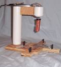
The chosen route for configuration was to use a magnetic
arrangement. Magnetic
levitation was chosen due to the decreased contact forces. The
only friction would be accounted for is the gases surrounding the
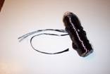
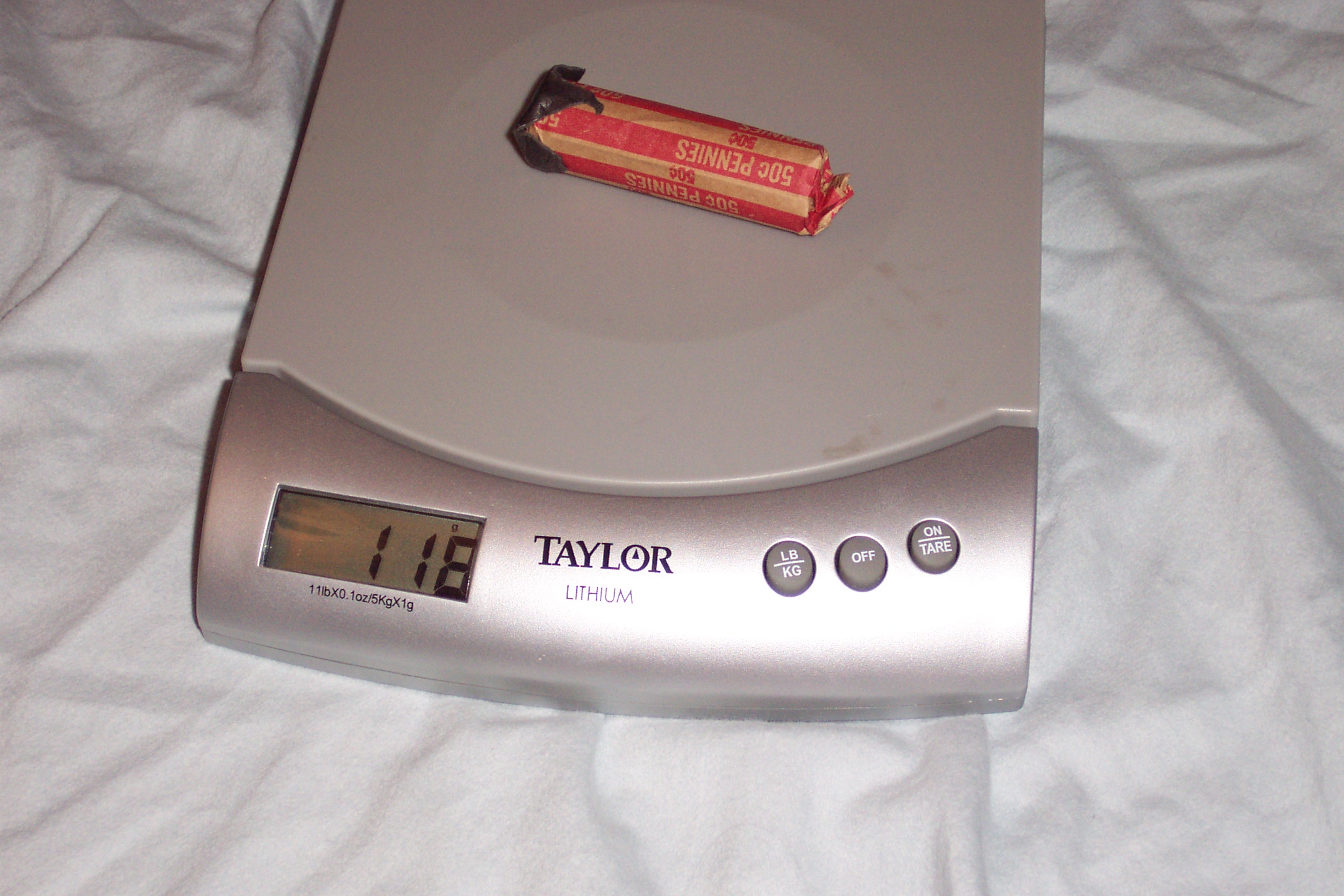
device. Test products were
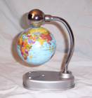
purchased and tested for proof of concept. The
original magnetic levitation device, a floating globe toy, was purchased
and redesigned for desired operation.
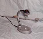
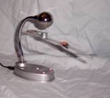
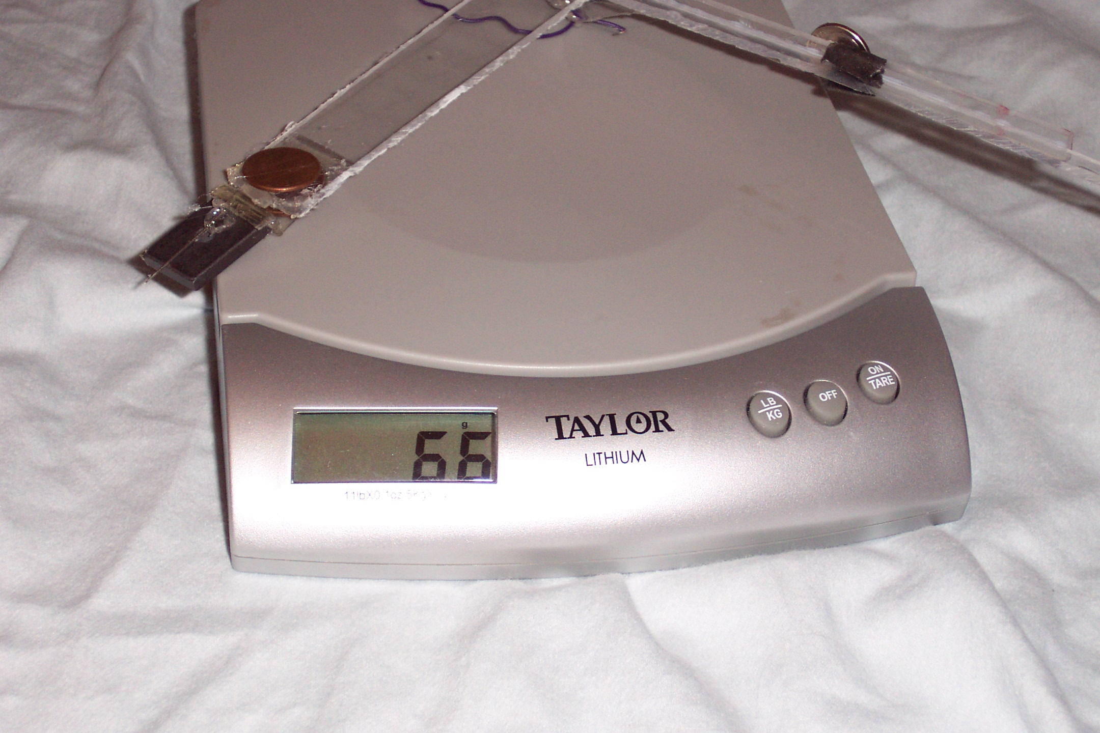
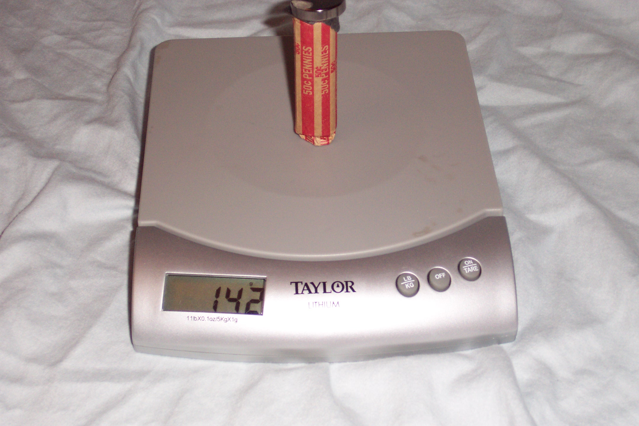
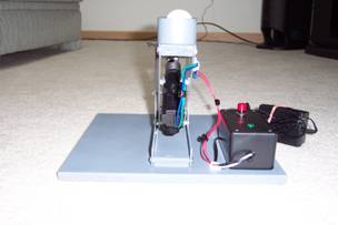
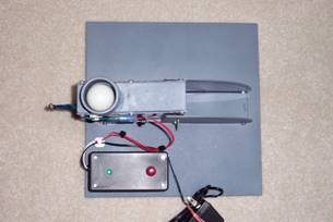
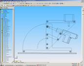
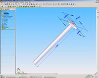
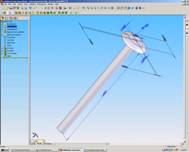
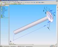
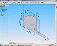
Pictures one through three provides rudimentary revisions of the
toy.
The magnetic levitation device proved to provide the desired low
friction and high sensitivity results.
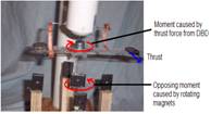
Additional problems arose after the analysis was complete.
The up and down pivoting movement of the DBD was able to be
counter acted by a weight on the opposite side of a pivot arm, although
the rotational movement, DBD thrust will require dampening with little
or no friction. Magnets once
again were implemented for connectionless restriction.
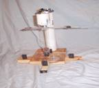
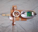
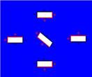
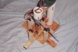
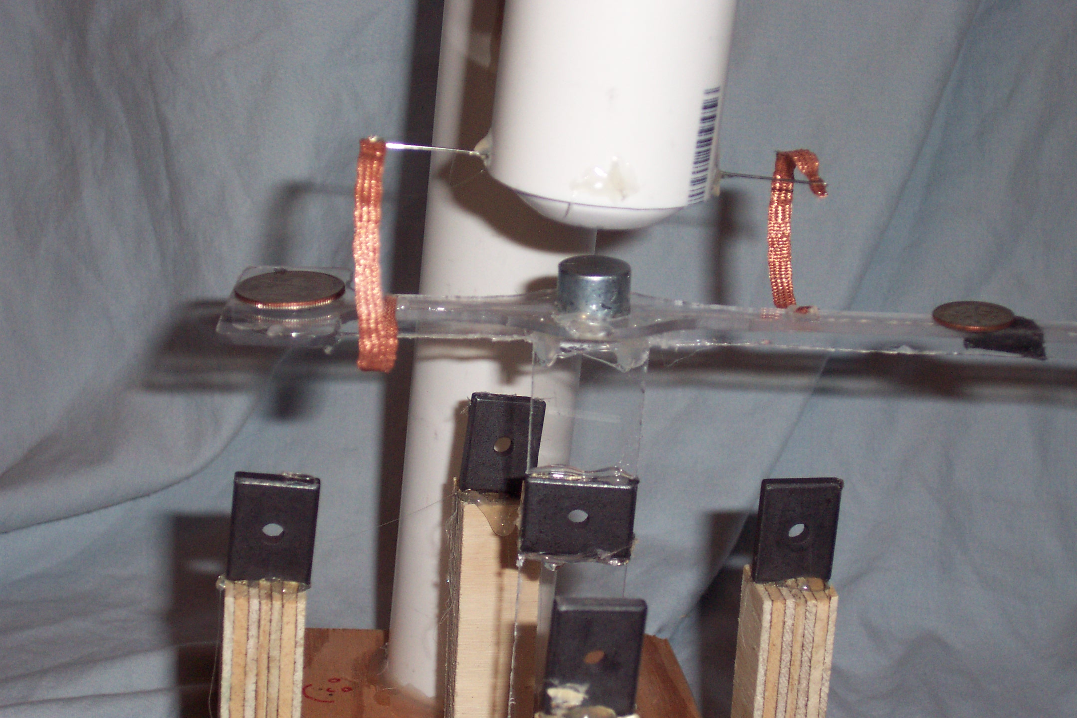
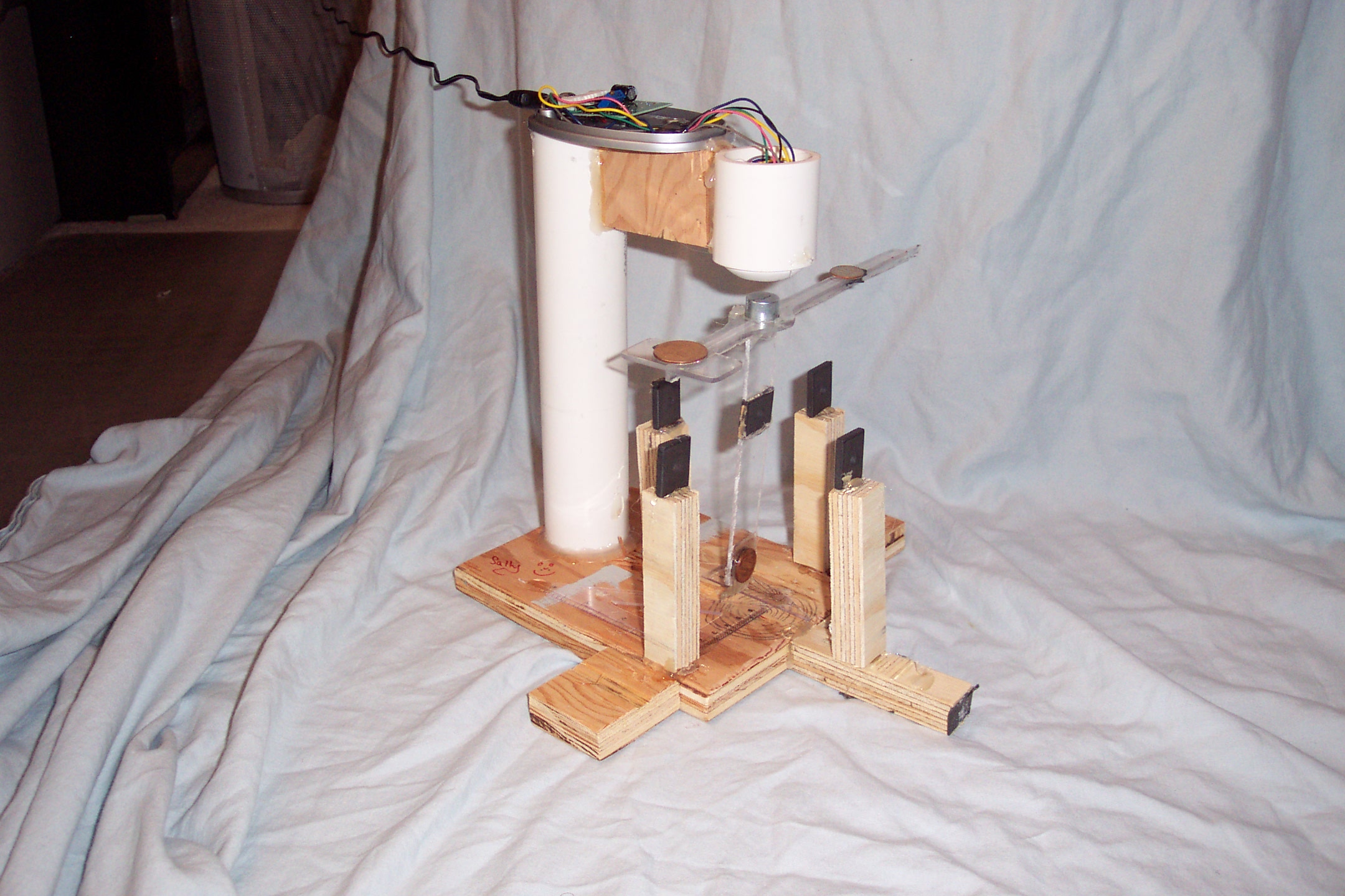
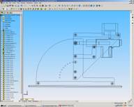
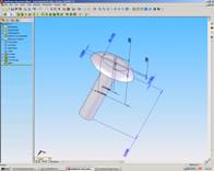
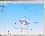
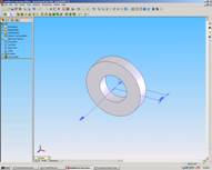
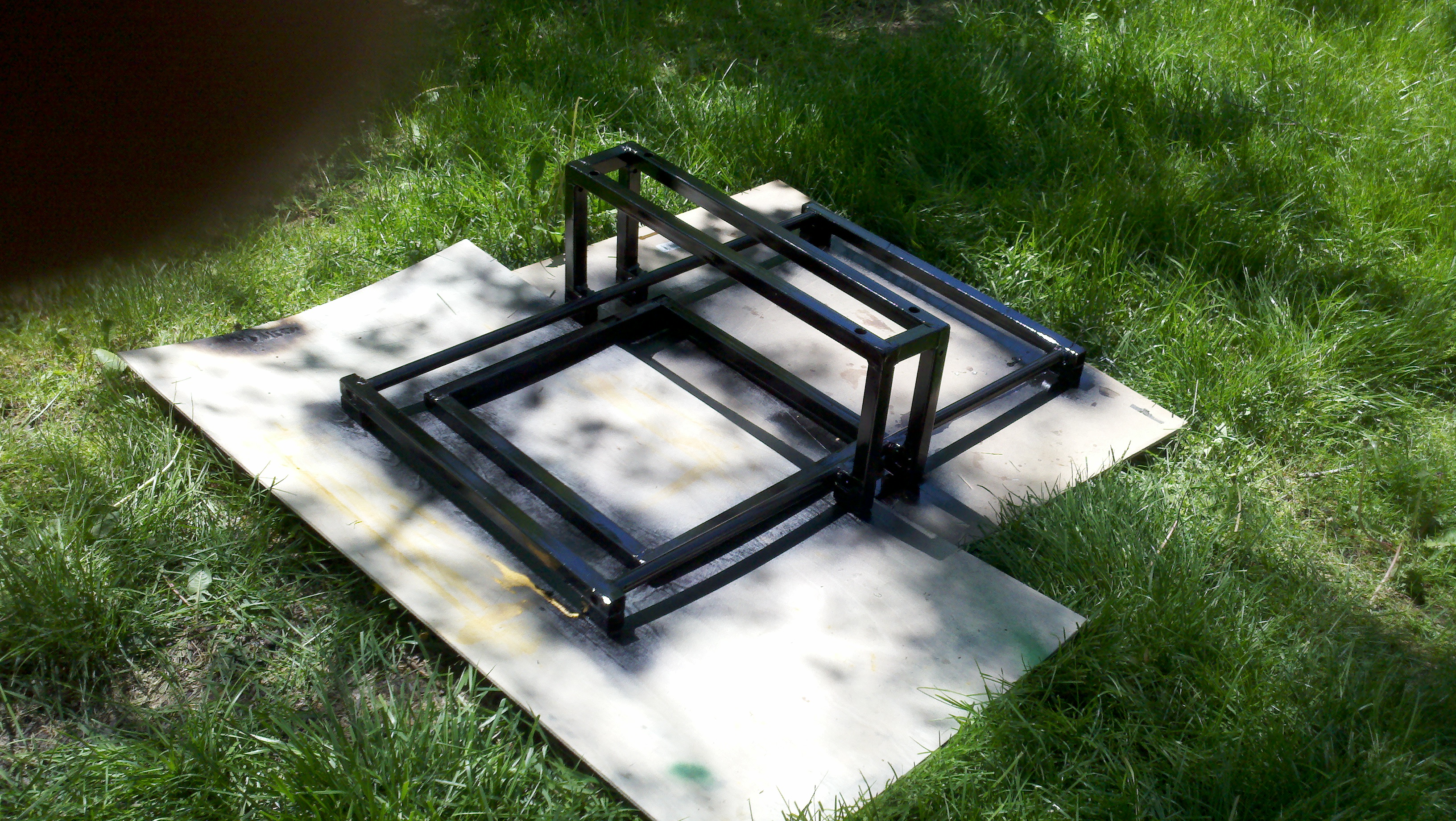
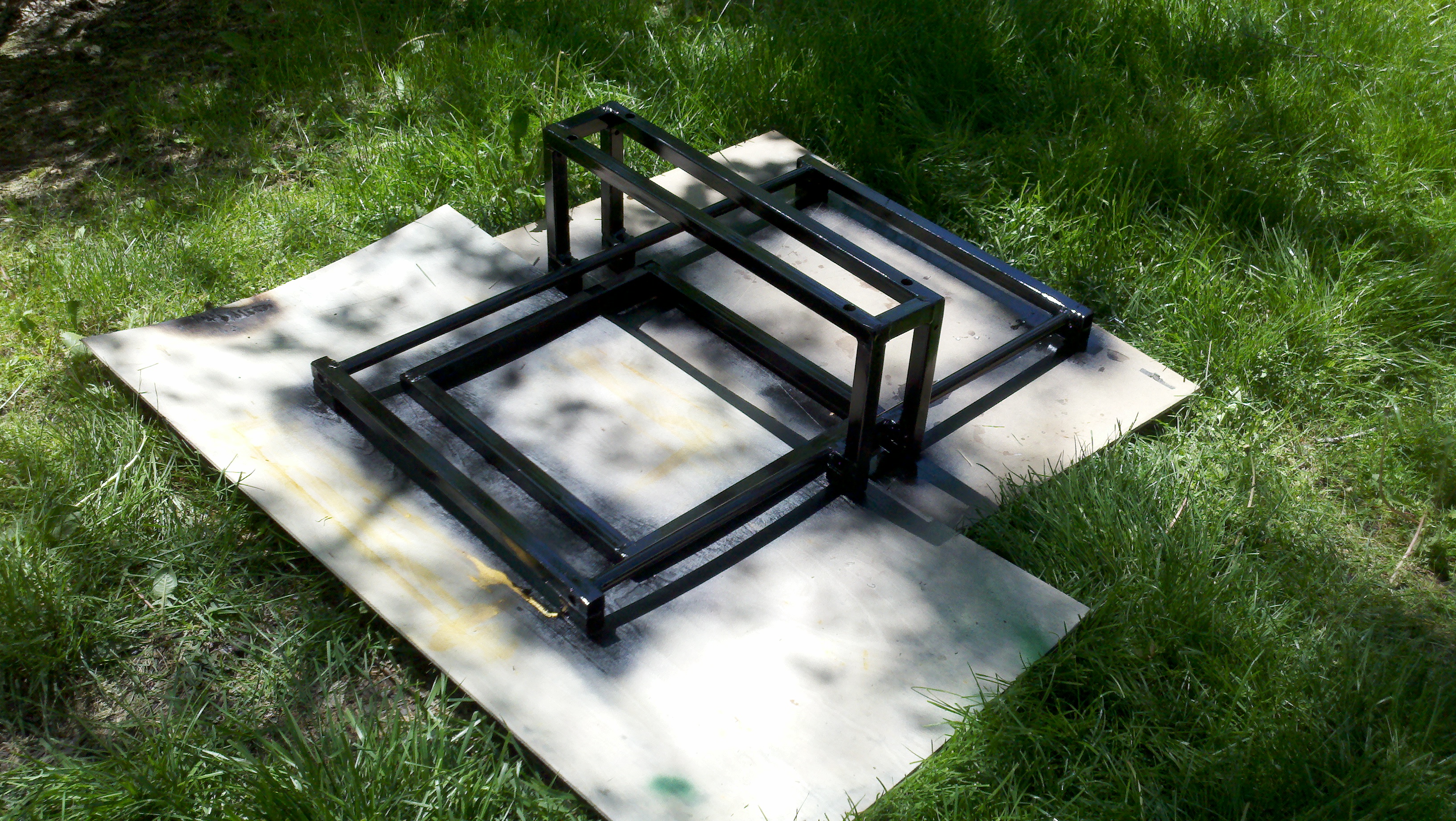
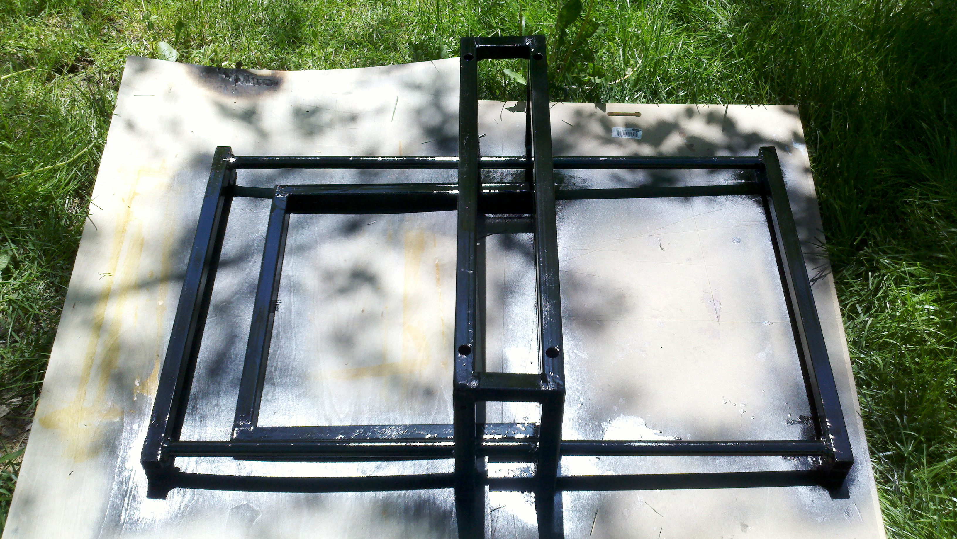
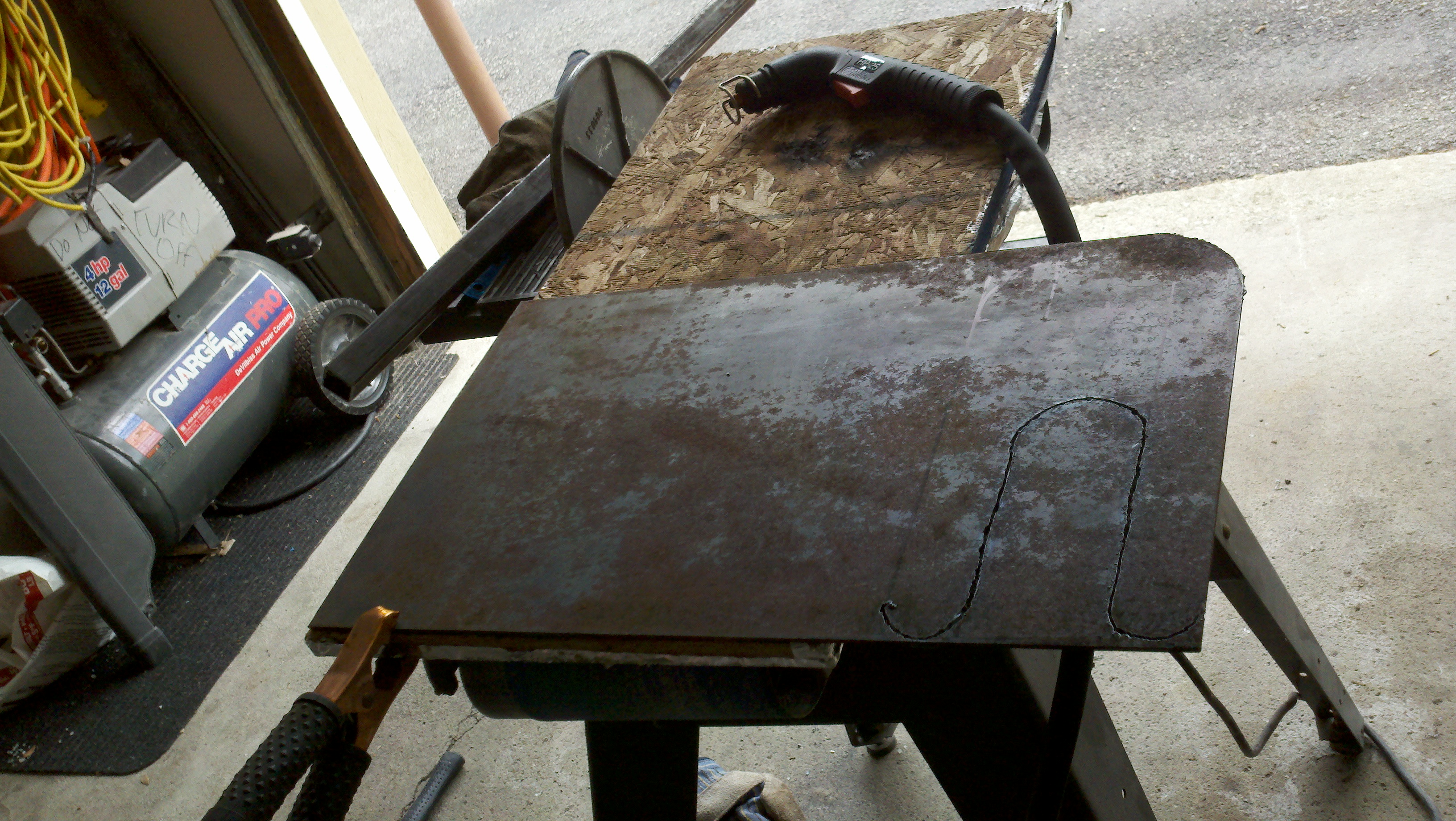
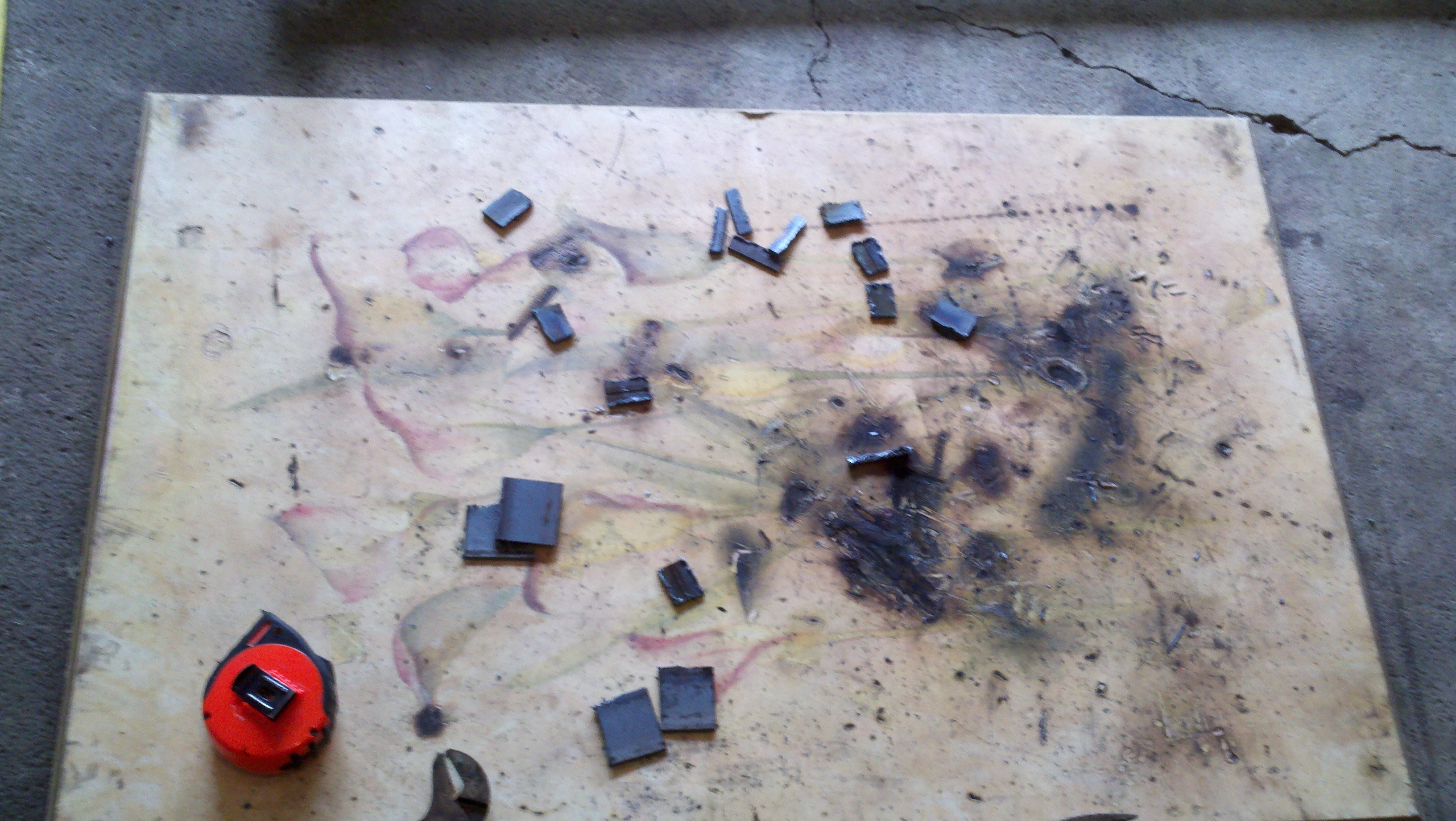
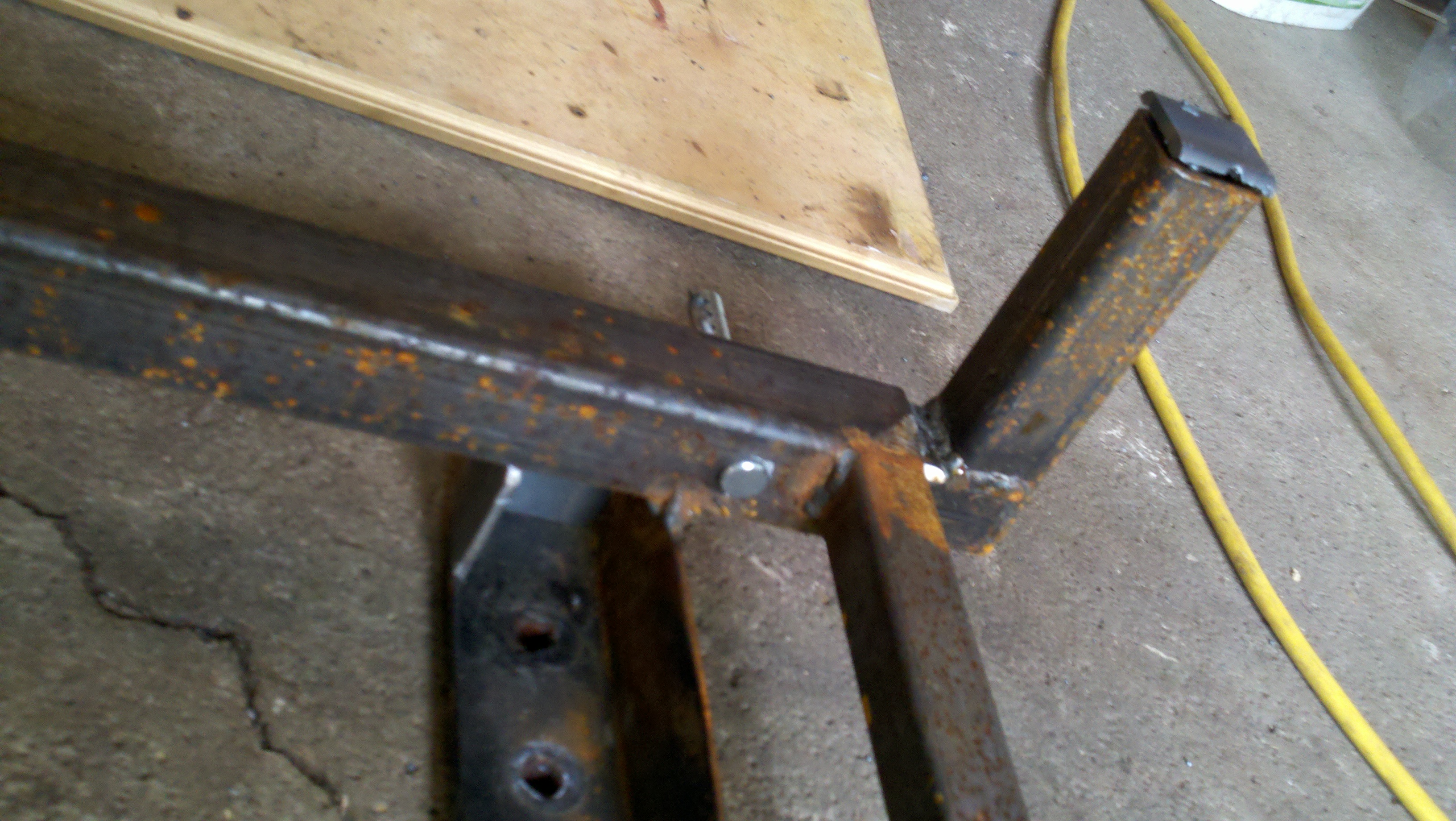
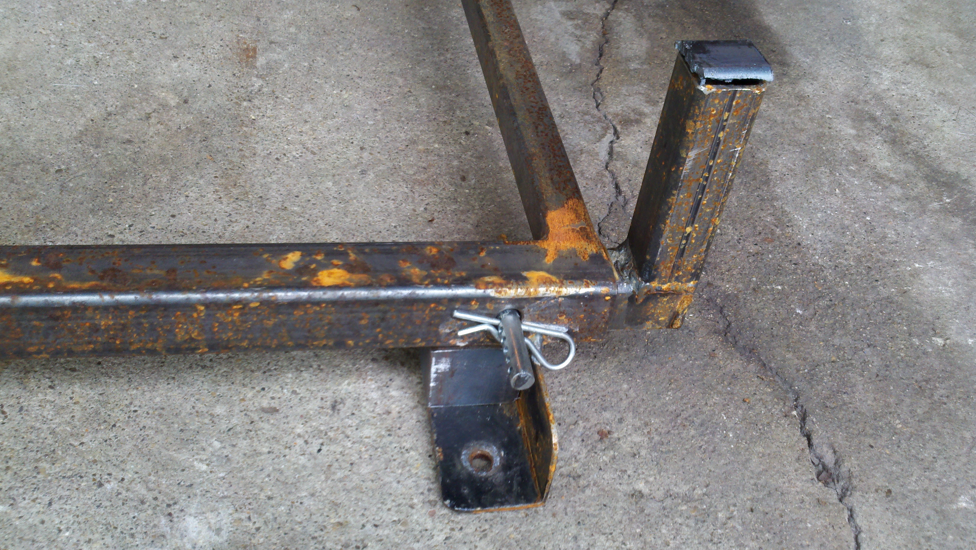
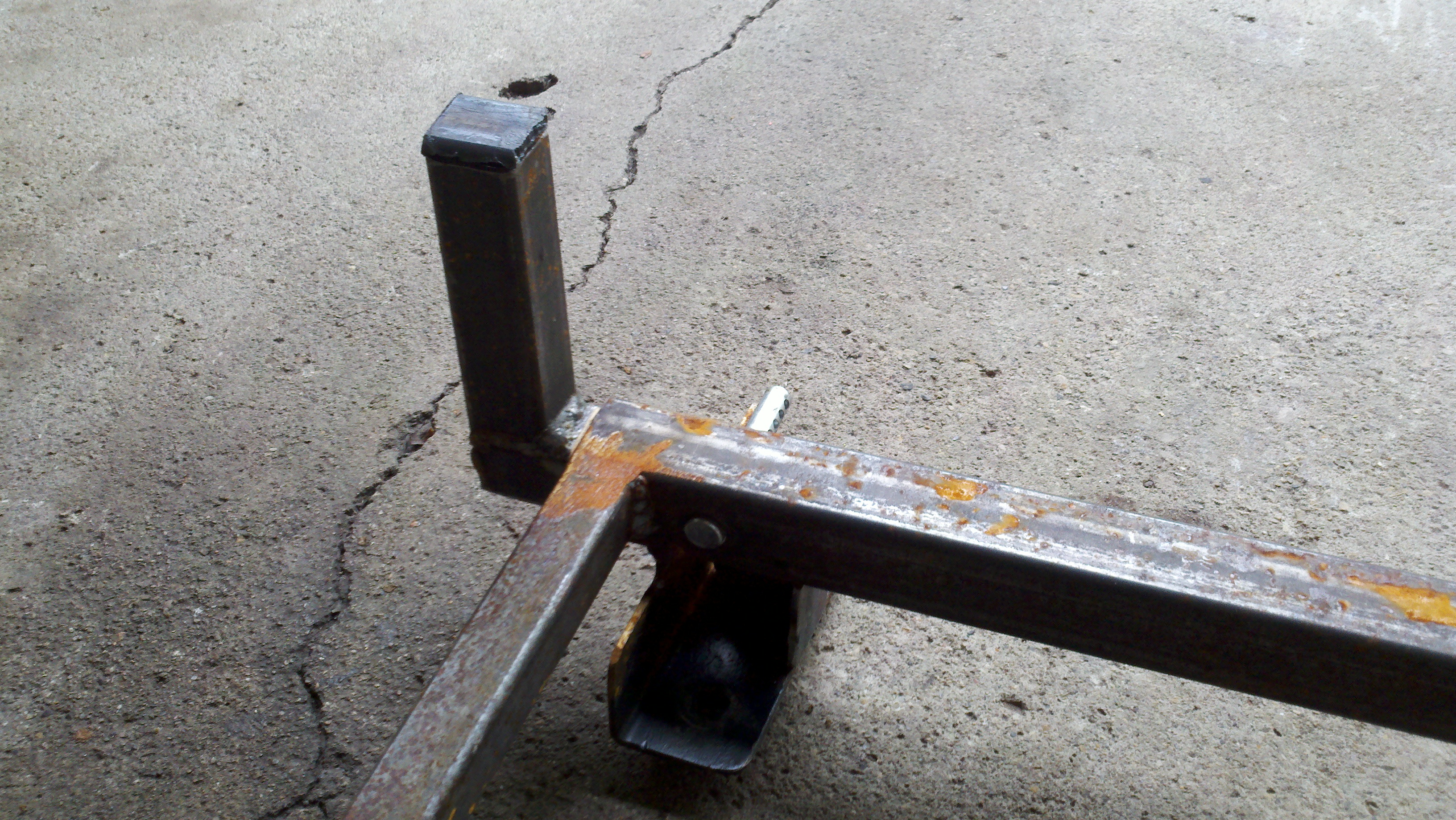
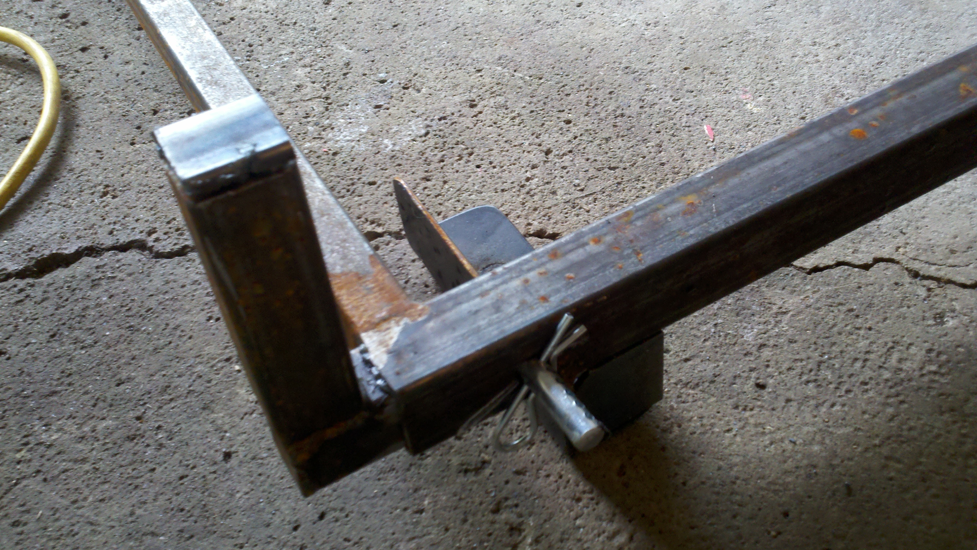
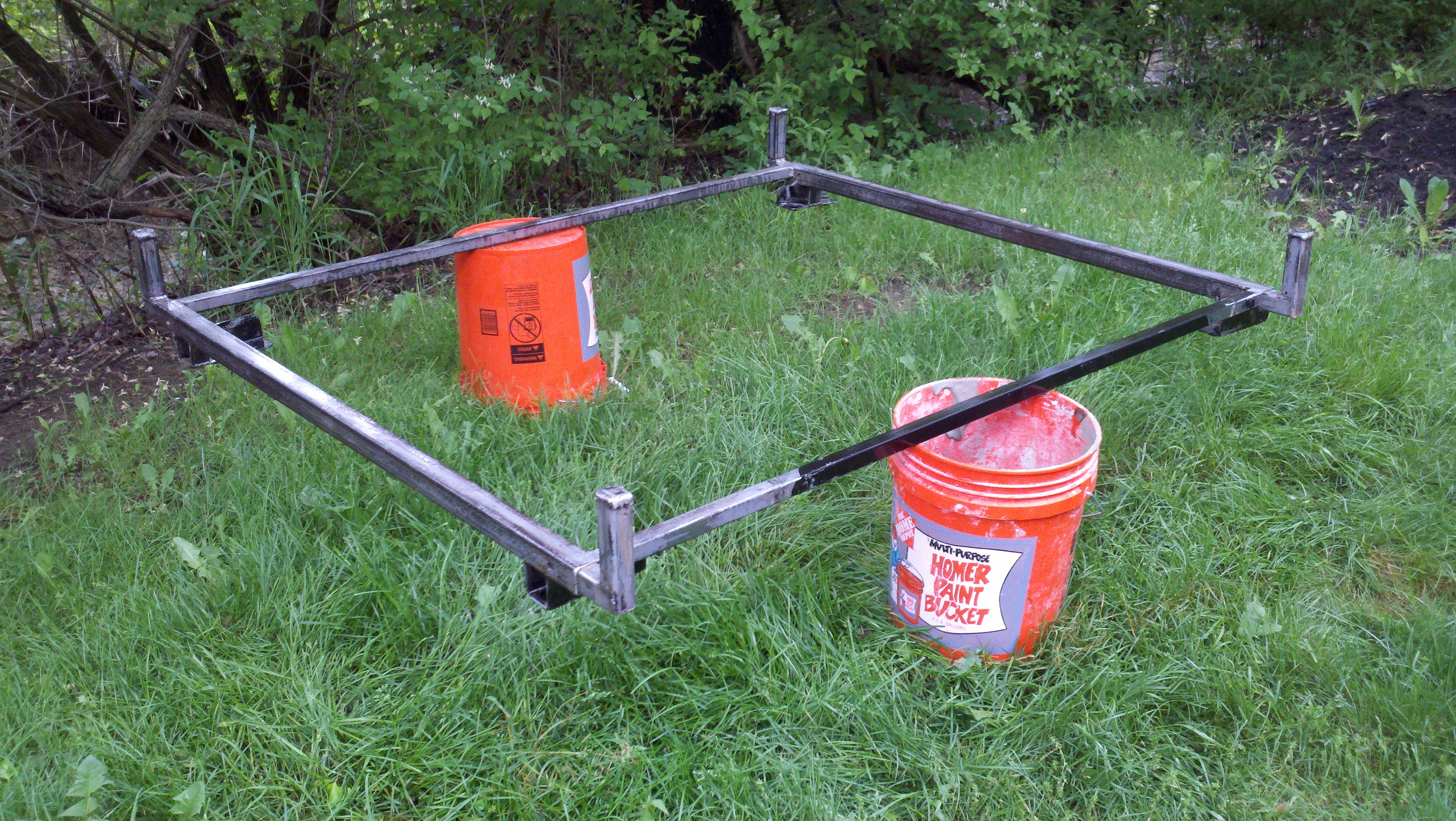
The pictures labeled four to nine provide accurate depictions of
a newly revised device with magnets and also a magnet arrangement
schematic. The magnet in the
center of picture eight requires a restrictive return to its natural
position attracting positive to negative sides.
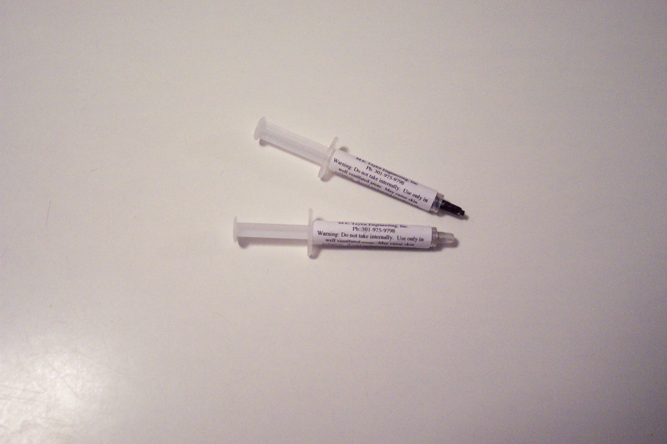
An additional problem further arose regarding the transfer of
voltage from the source to the DBD.
Friction was still a repeating issue that would not provide any
forgiveness for this new issue. An
idea about using carbon fiber jute was introduced due to the
conductivity and flexibility possibilities.
The new venture succeeded. The
carbon fiber has low resistance and is very flexible.
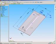
The following illustrations provide visual aids including the
carbon fiber connections and a magnetic restriction diagram.
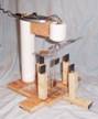
The next step was to purchase an increased size magnetic
levitation device that can provide a levitating capacity of 250 grams.
A larger globe levitation device was found and implemented into a
larger copy of the original small test device.
Further alterations were integrated into the design for magnet
adjustment and damage prevention. An
additional prospect was the addition of sensors to provide an electrical
signal that will provide information regarding the measurement of the
device through position of the pivot arm.
The project time restrictions prevented completion of this task.
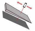
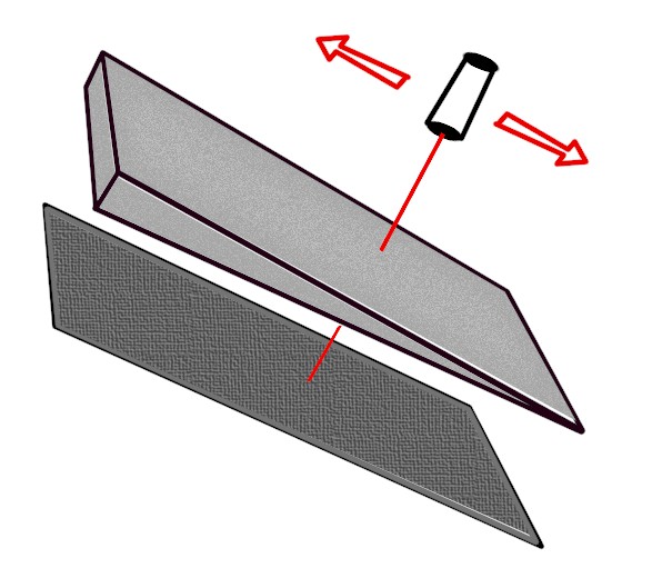
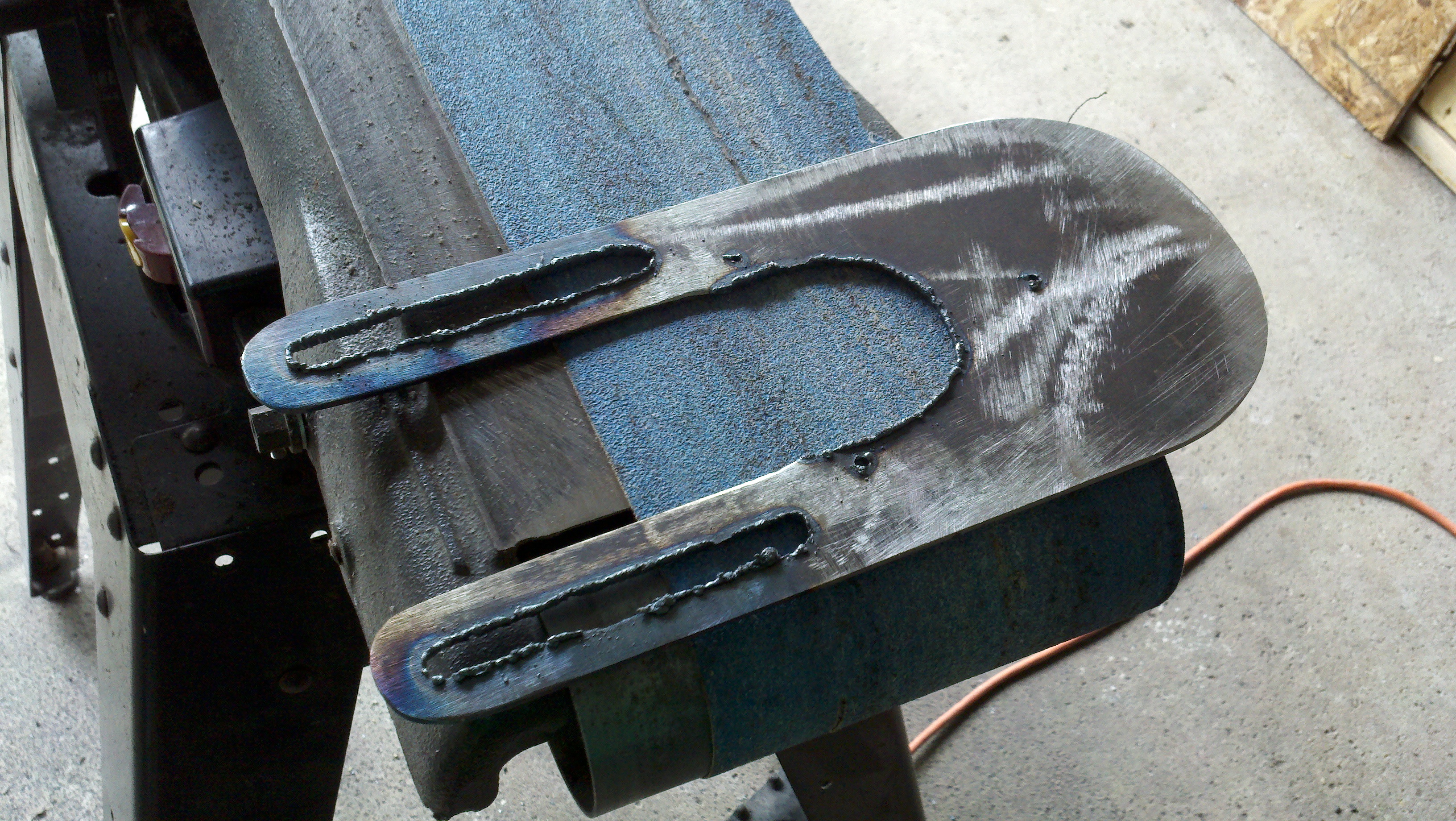
Angled tinted plastic, laser, and solar panel was chosen for the
recording device. The
movement of the laser linearly along the plastic wedge projected an
increase or decrease of light on the solar cell providing a decrease or
increase of voltage. The
voltage output could be potentially recorded by a program calibrated by
the group to display the recorded force.
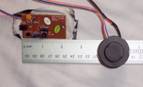
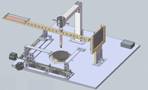
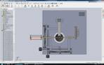
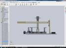
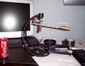
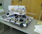
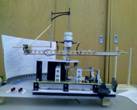
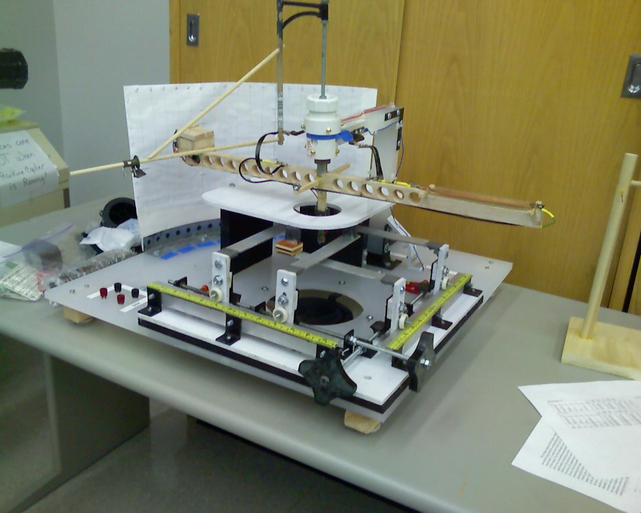
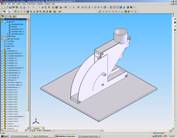
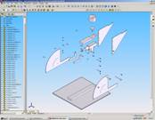
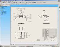
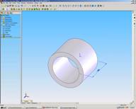
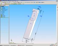
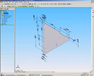
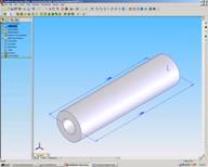
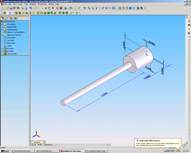
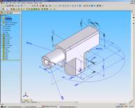
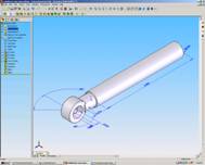
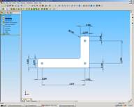
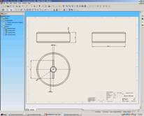
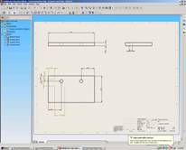
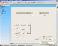
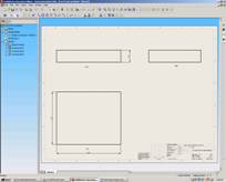
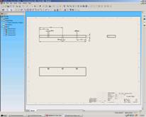
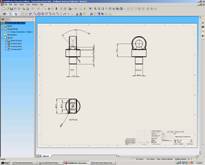
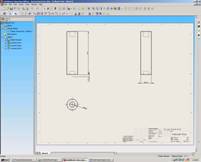
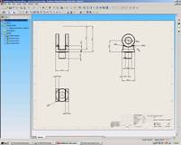
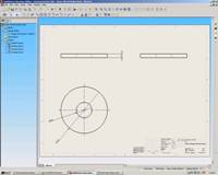
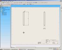
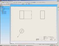
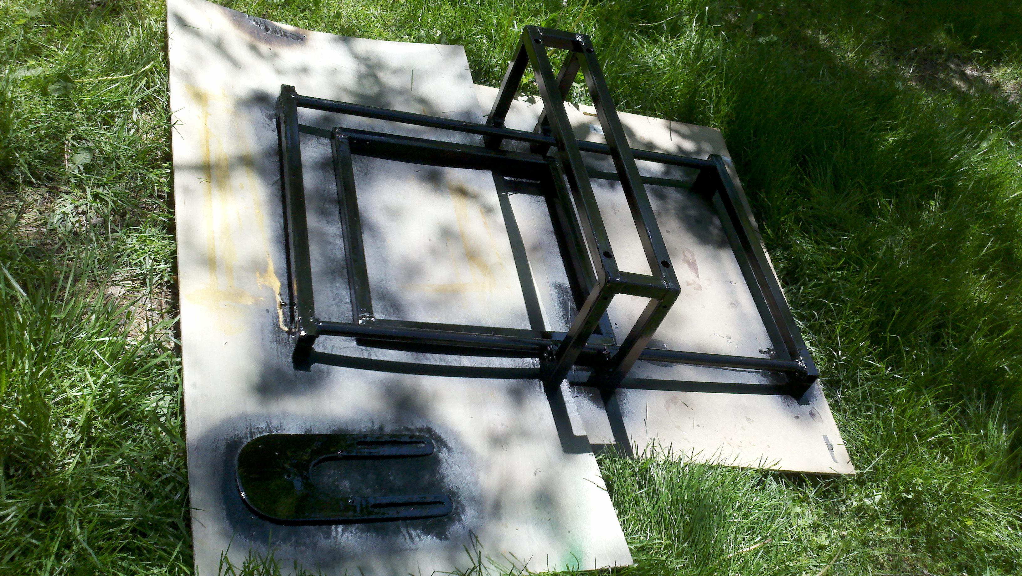
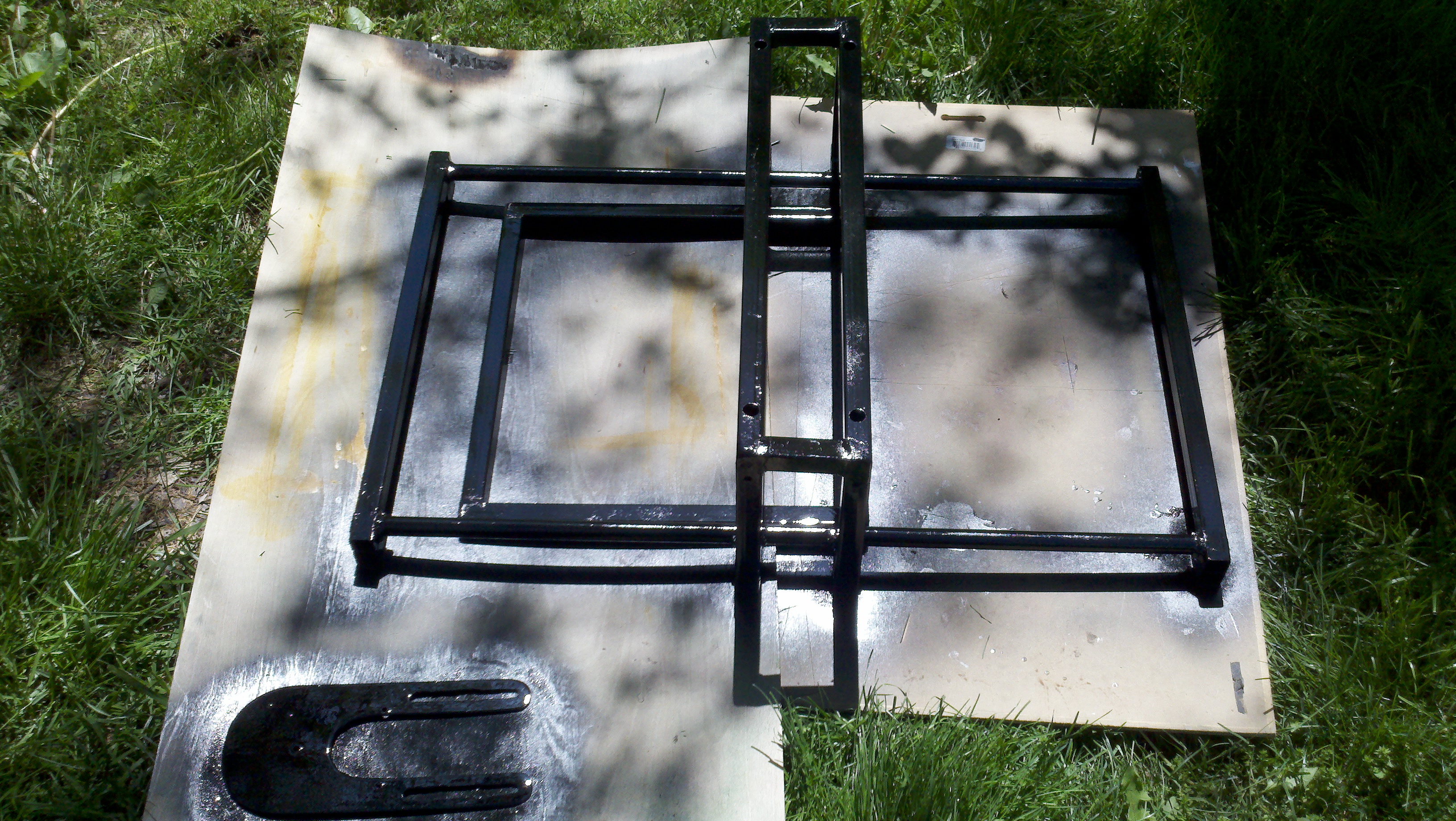
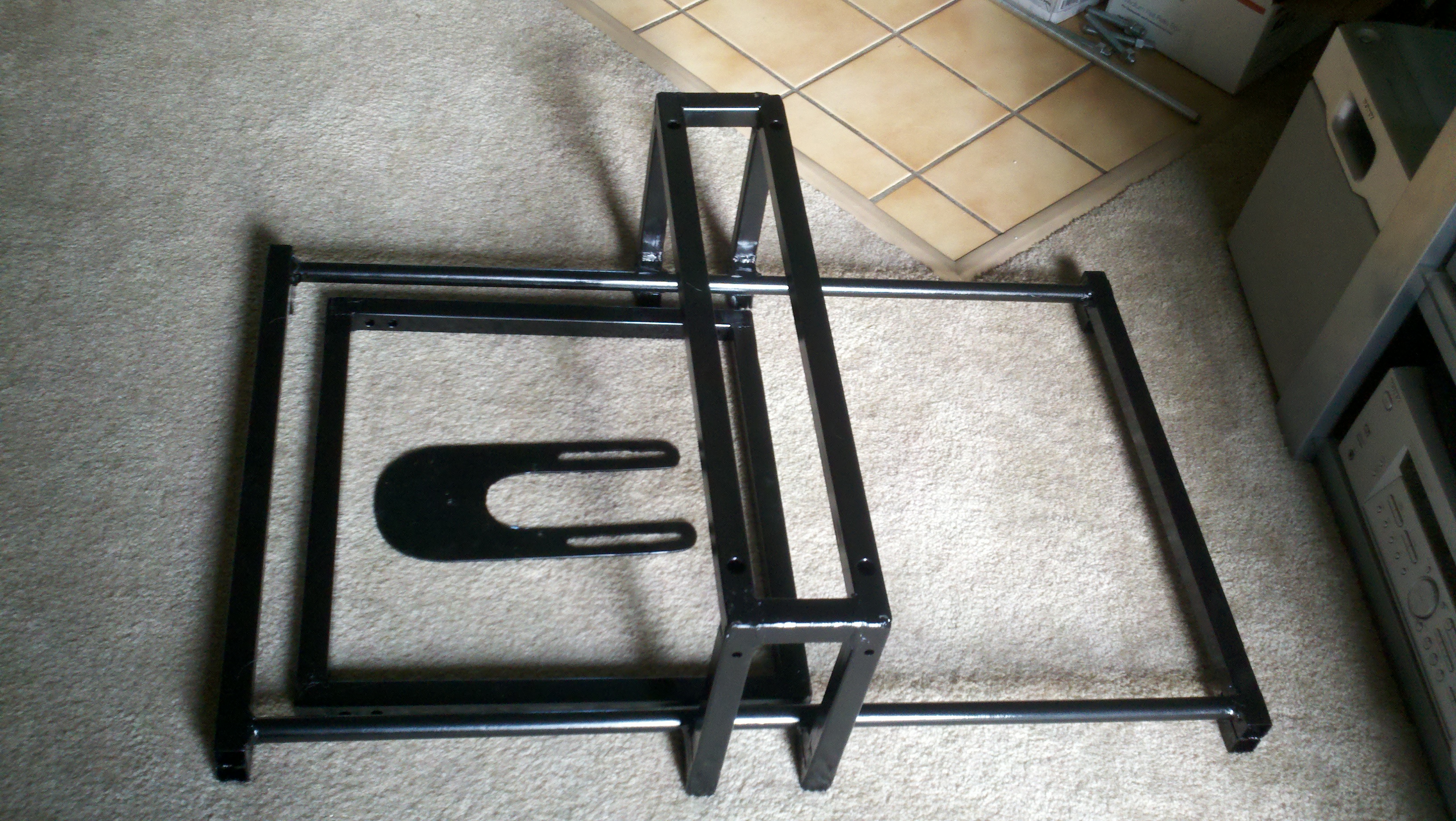
Pictures below provide visual information about the sensors,
SolidWorks drawings, and the final version of the DBD measurement
device.
|
|
|
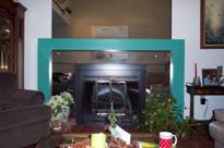
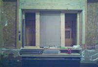
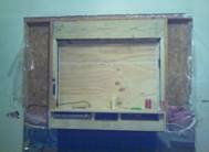
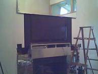
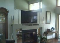
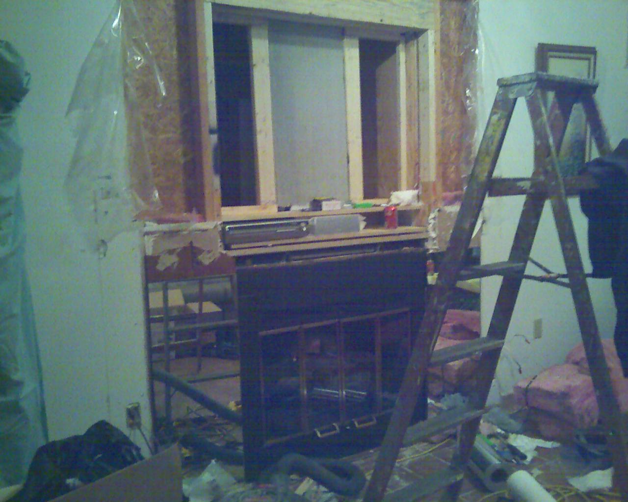
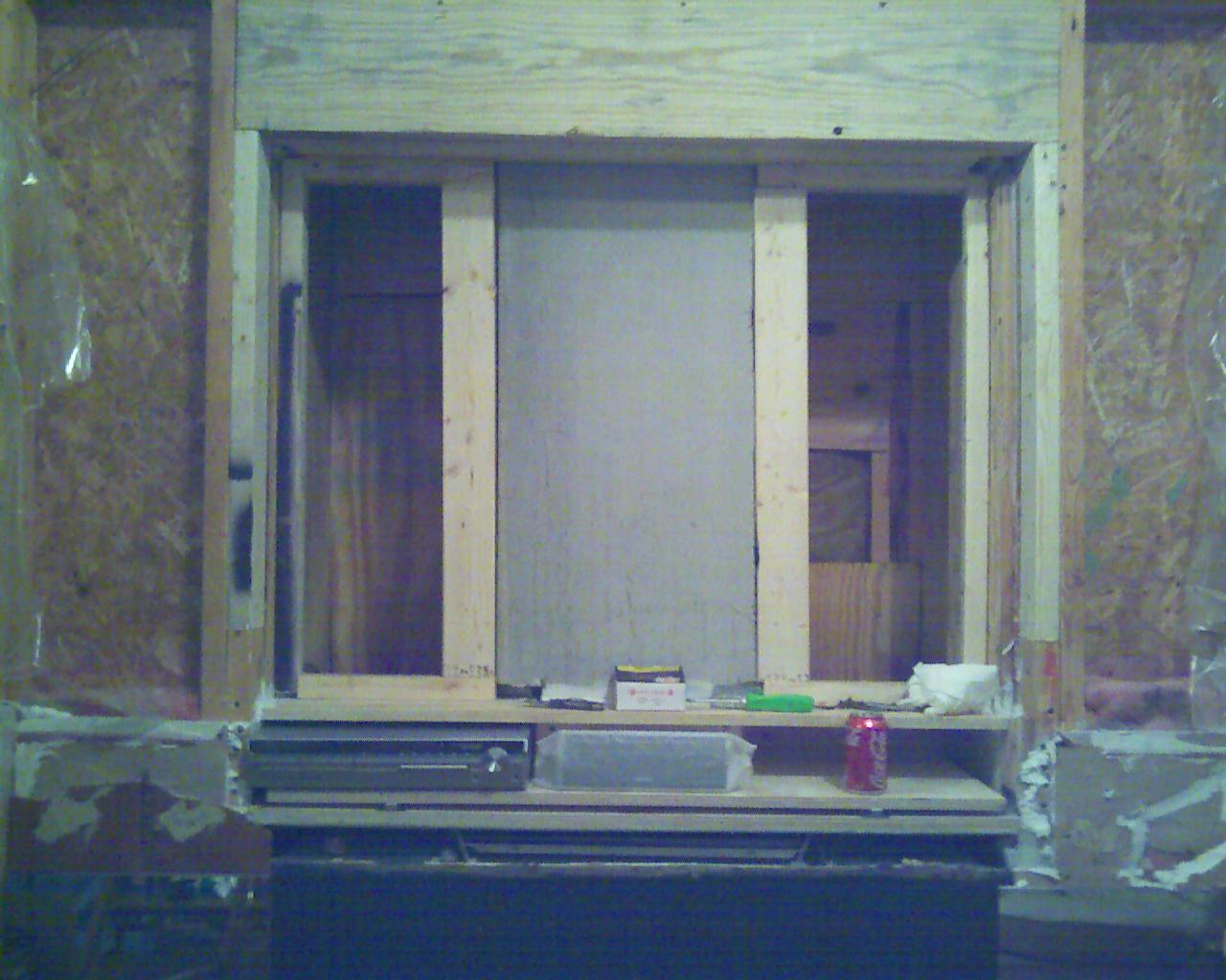
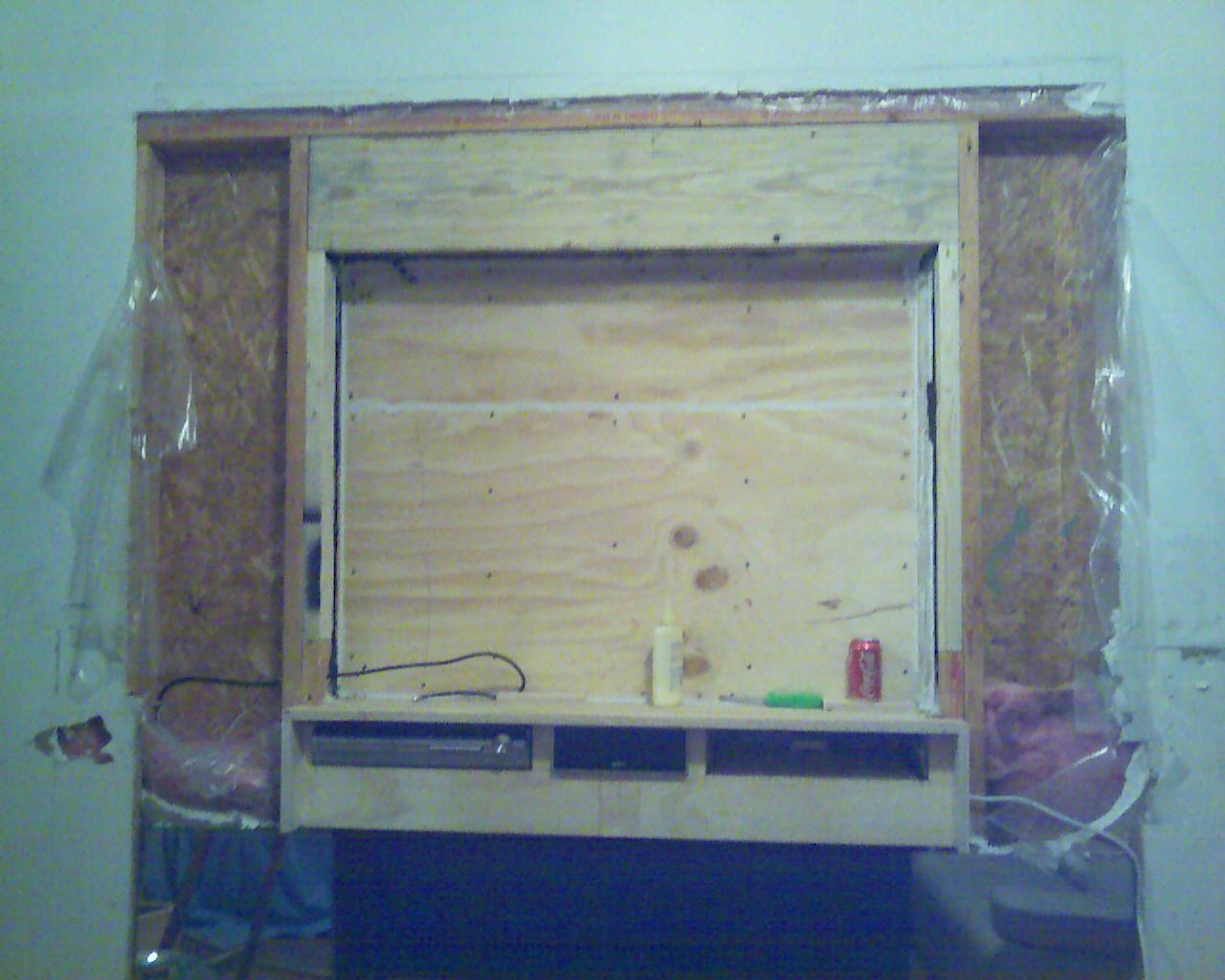
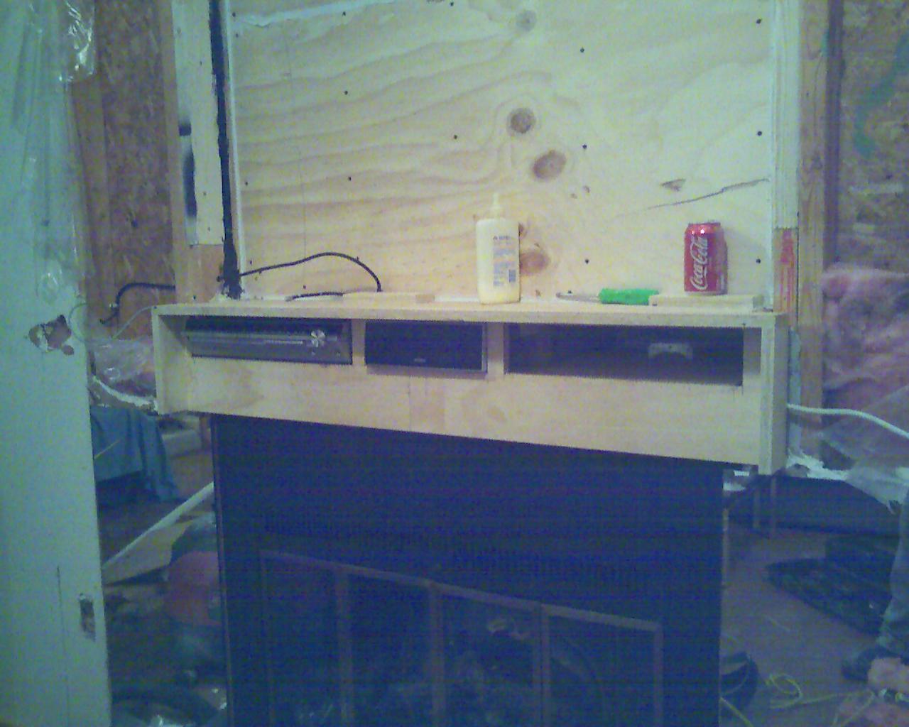
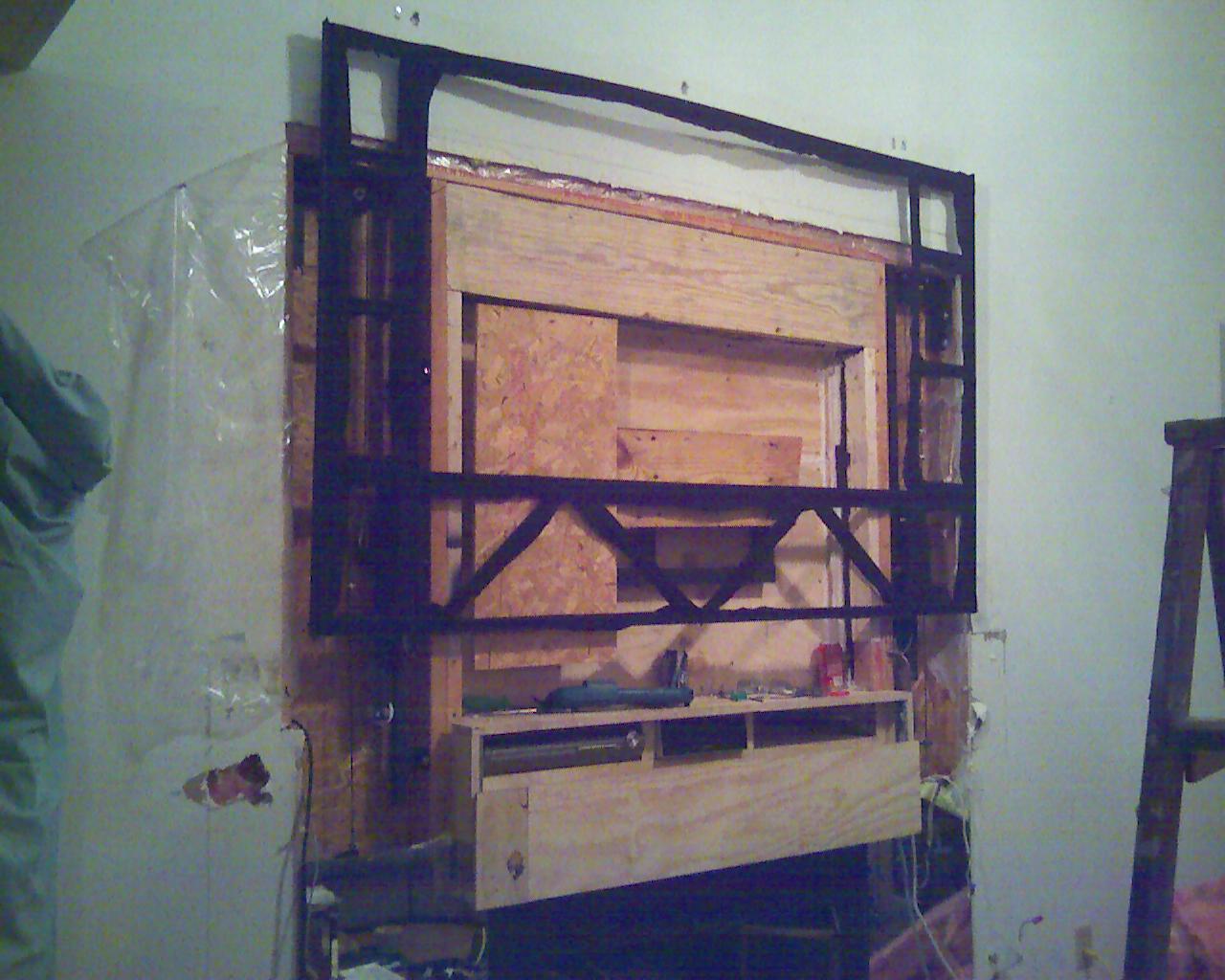
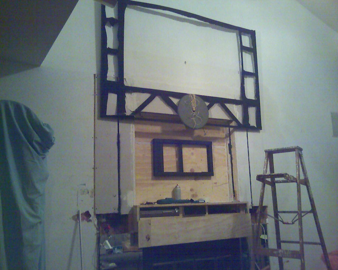
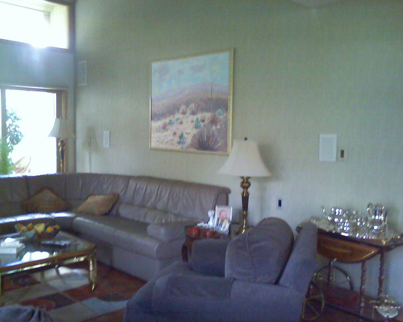
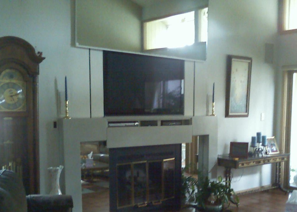
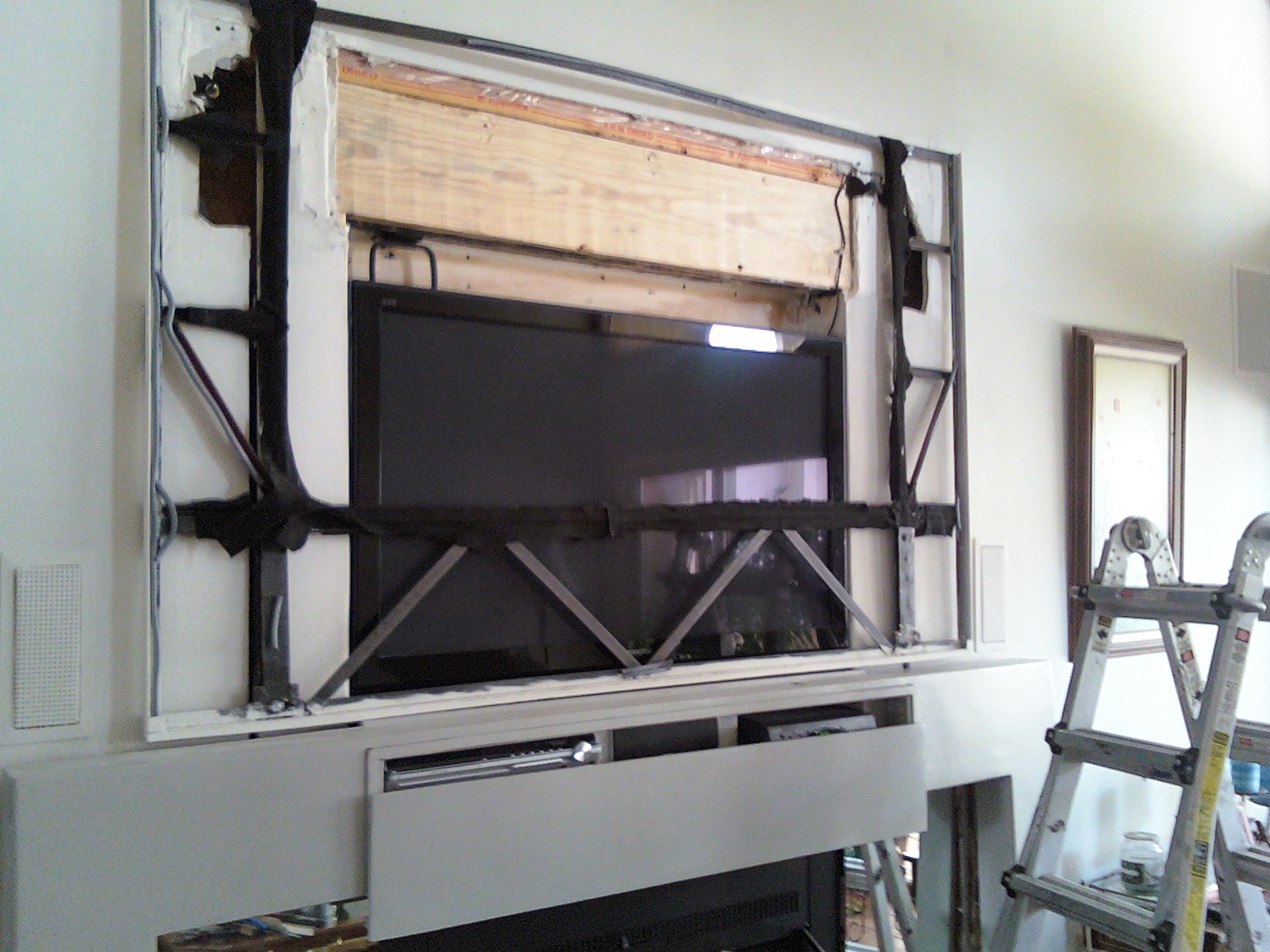
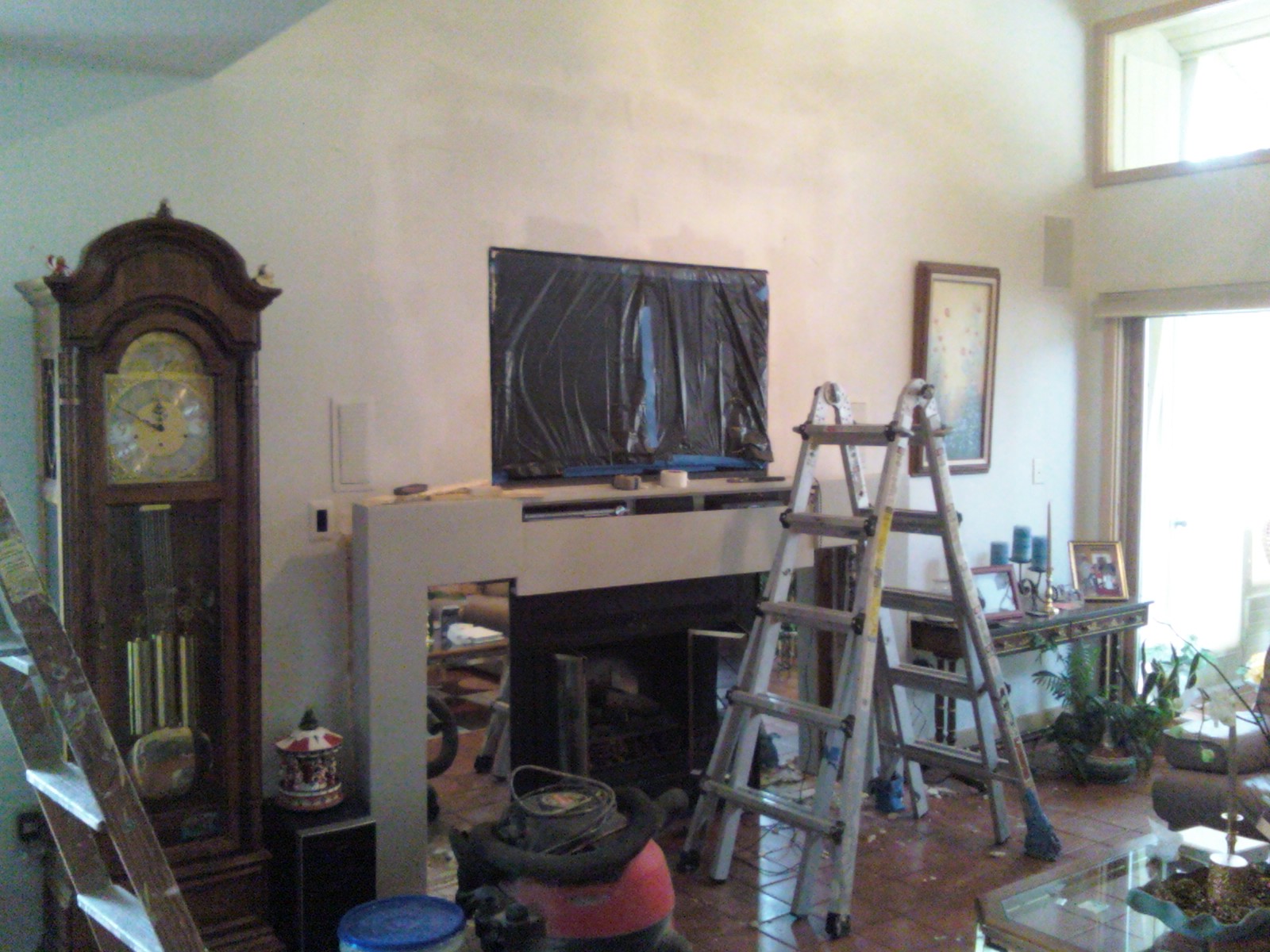
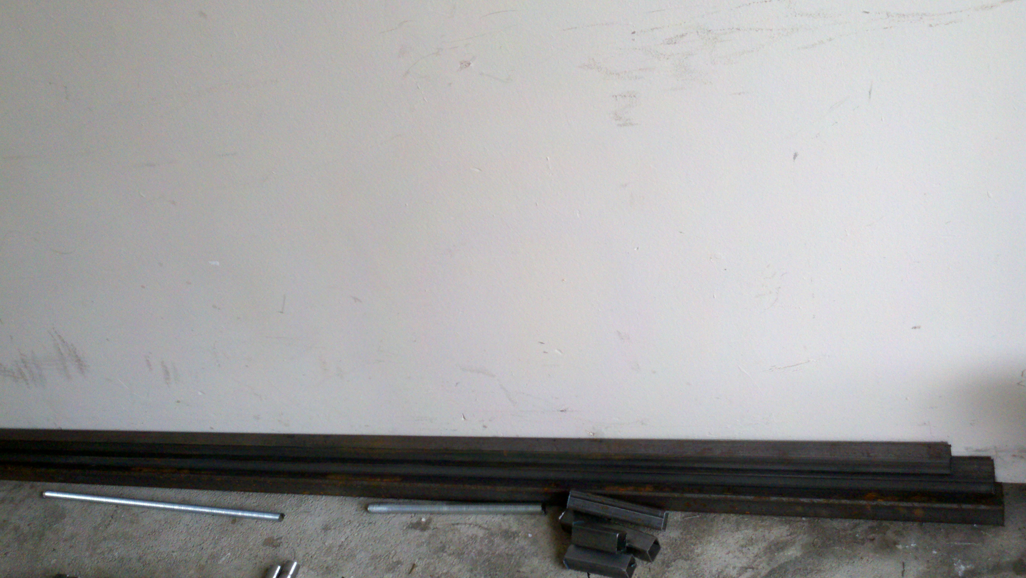
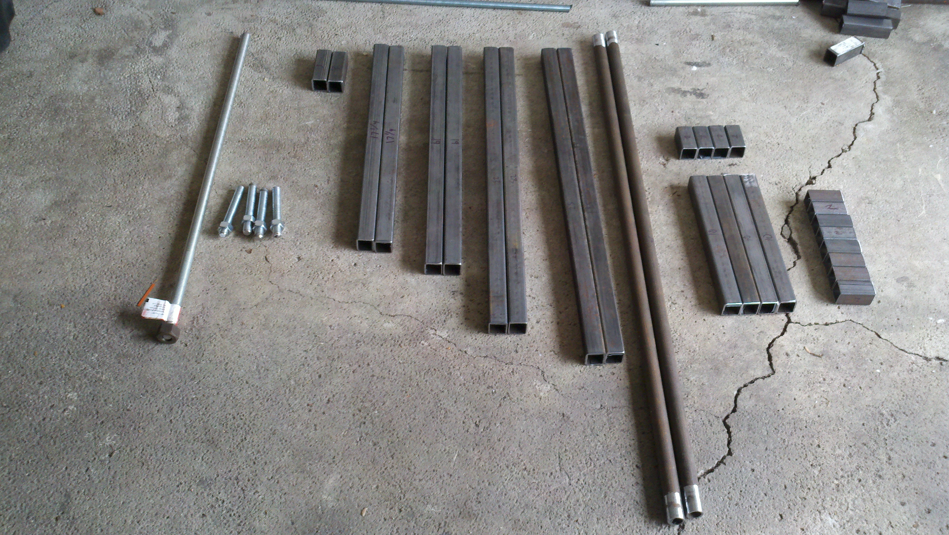
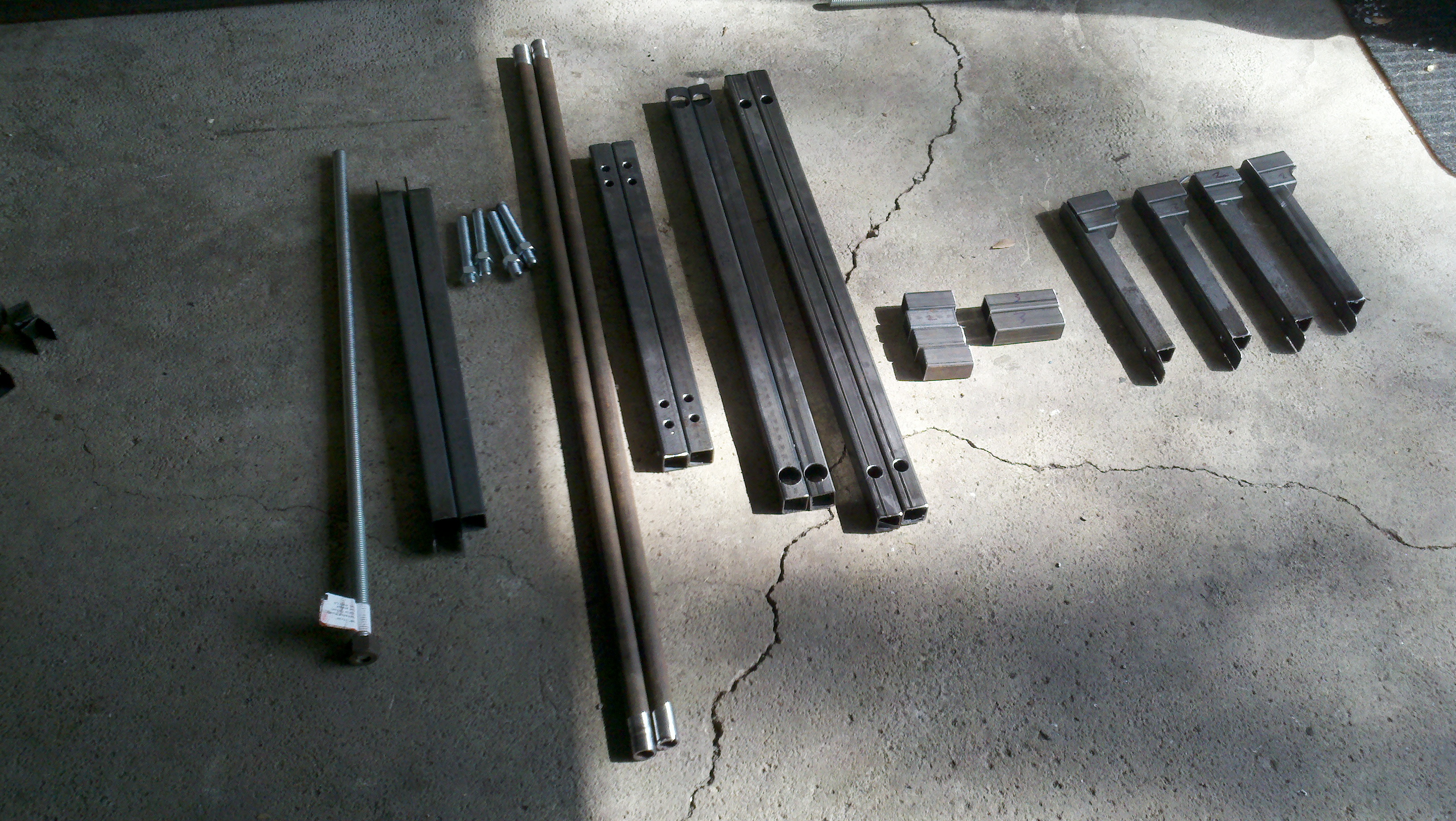
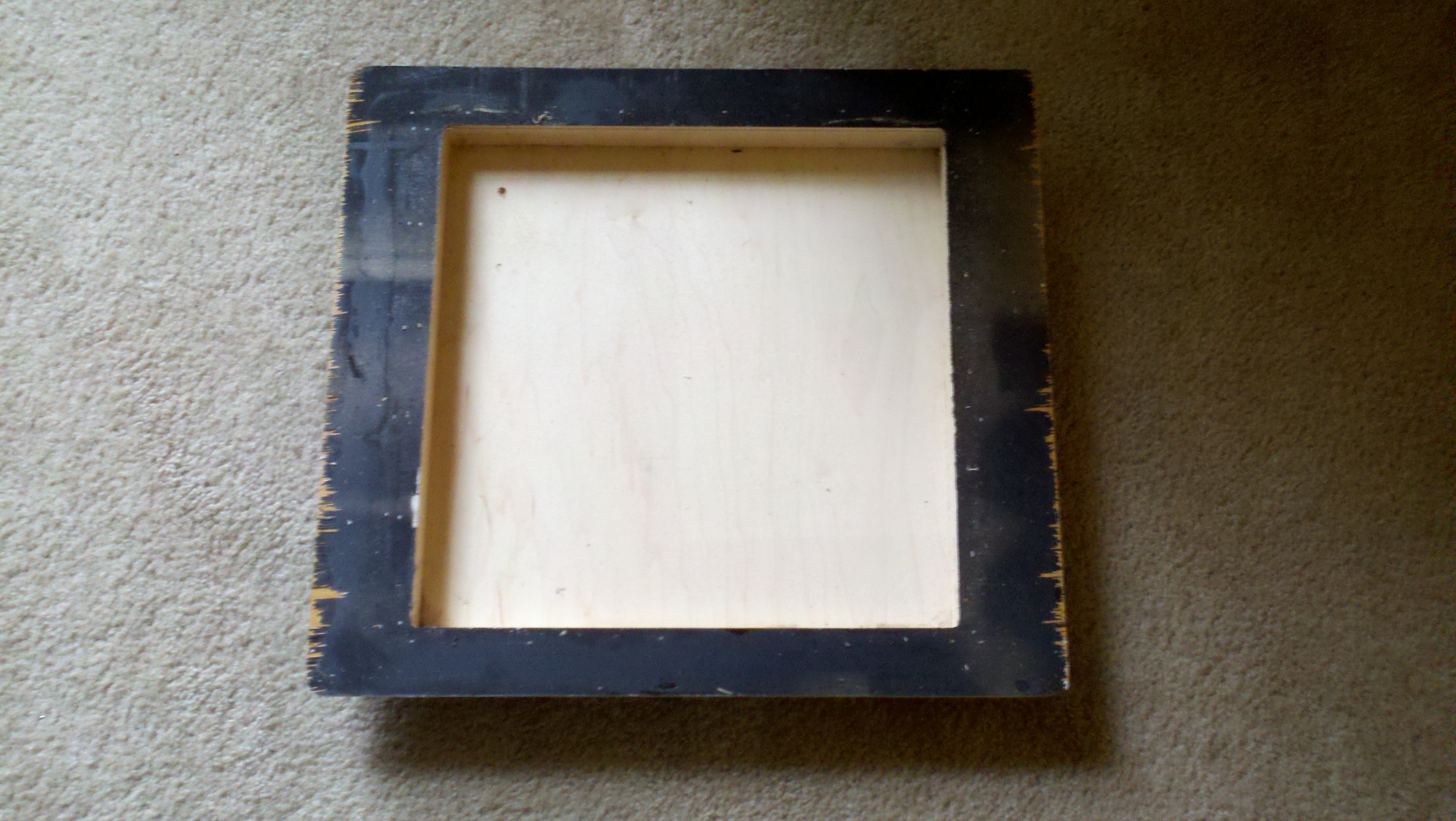
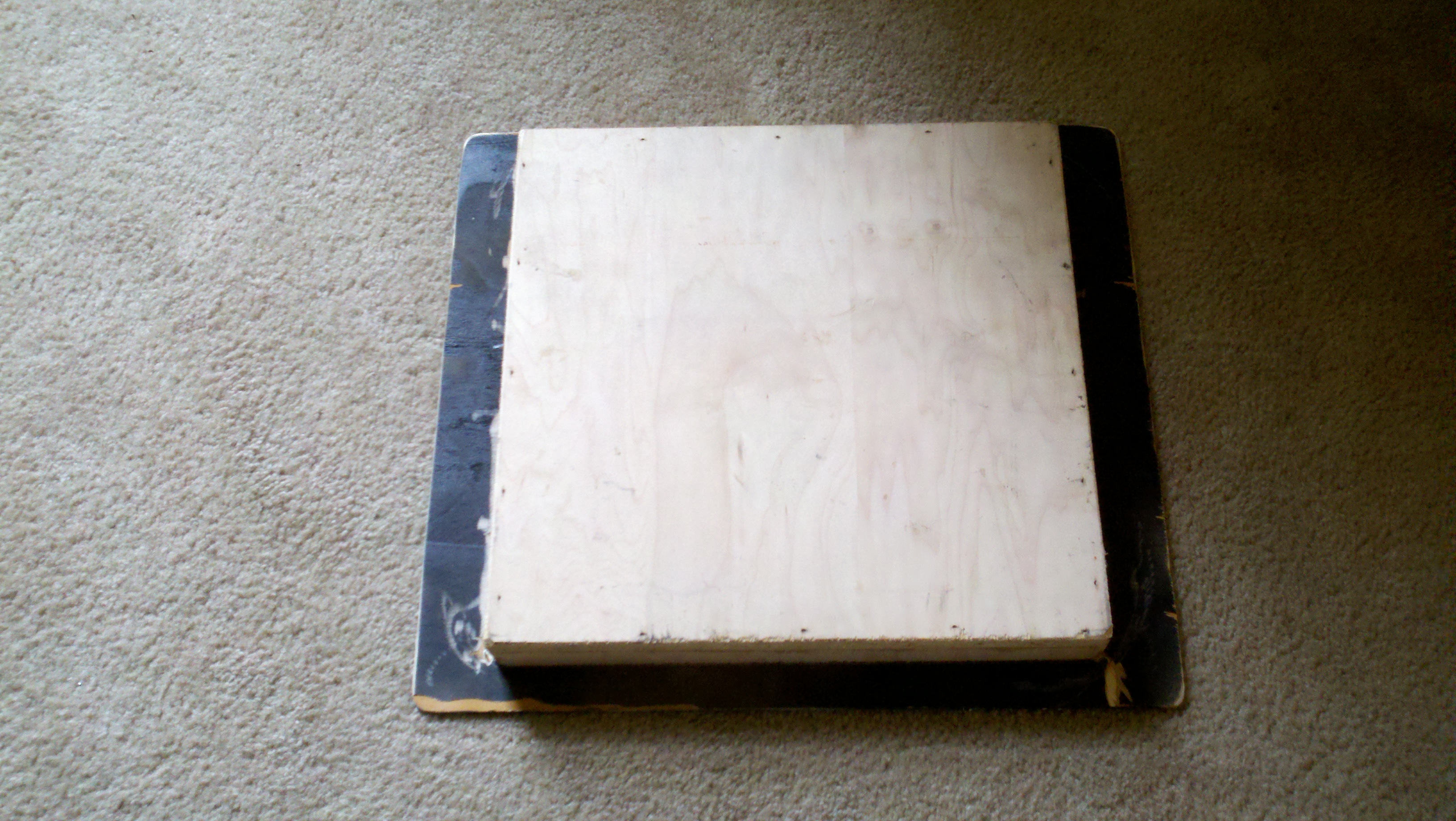
Motorized Mirror and Mantle Refigure Design, creation, and fabrication of a vertically traveling motorized electrically controlled mirror with assistance by a combination of counterweights and pulleys. The design implication was required due to the need for a larger television installation in a formal living room. Visual aspects of the television, cable box, and surround sound equipment were restricted to be seen only during desired visual or audio experiences. The following pictures represent the task of tear down and rebuild of the mantle. First picture shows the original form of the mantle. Picture two through four provides a visual representation of the deconstruction and manipulation of the wall to accept the electrical equipment and insert the plasma television behind the mirror. Exceptional care was provided by inserting a cement enclosure surrounding the electrical equipment to reduce the possibility of overheating or destruction due to an intentional fire created in the fireplace.
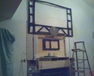
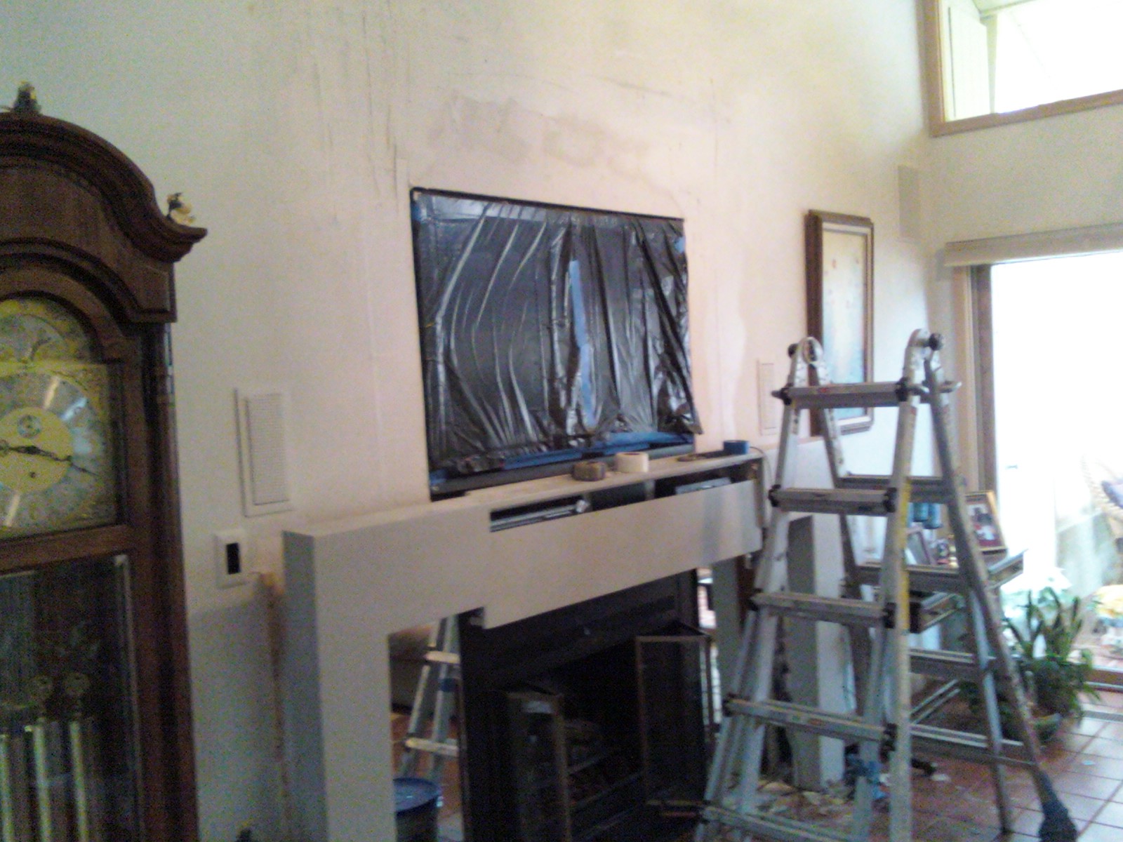
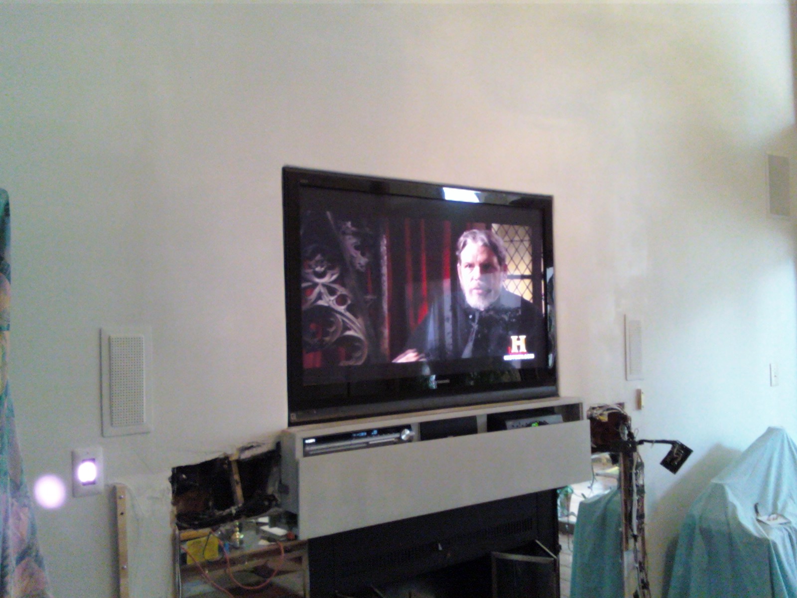
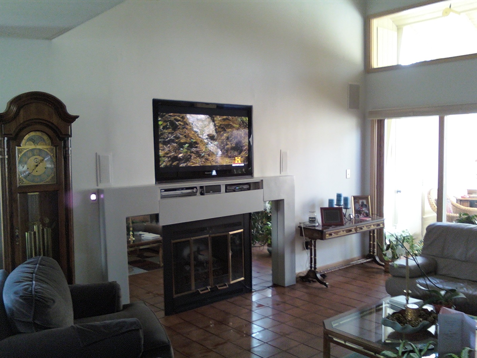
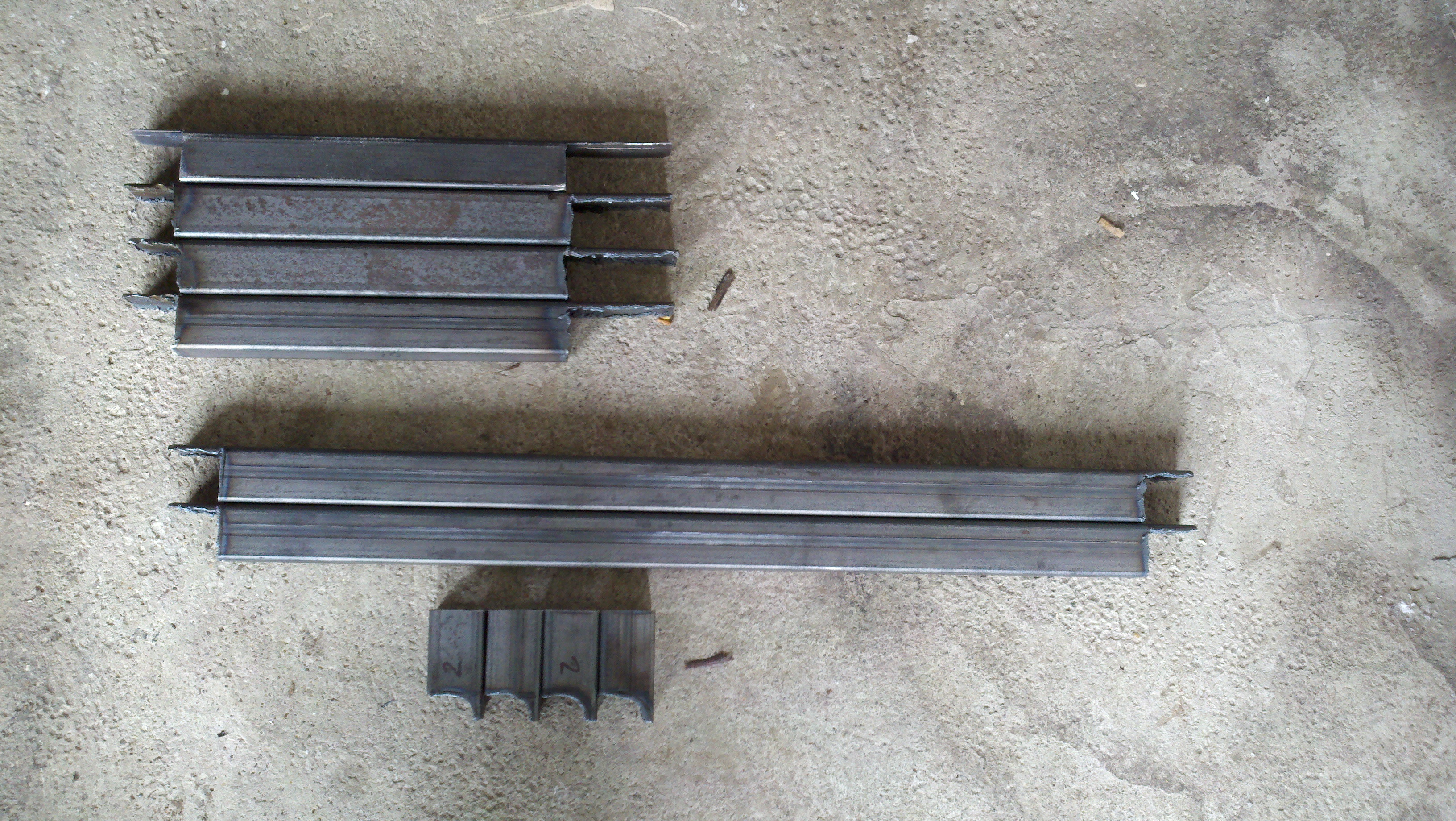
The next three pictures vaguely show the configuration of the counter weights, guide rails, pulleys, mirror slide frame, and component drawer. Other notable aspects, of these pictures, are the hand configured steel components for the television, slide rails, slide rollers, and mirror mount. The component drawer is configured to completely roll out for component accessibility for possible repair issues. The seventh picture shows the mirror located in the upward position and the final form of the dry wall; after seam sealing, sanding, and paint.
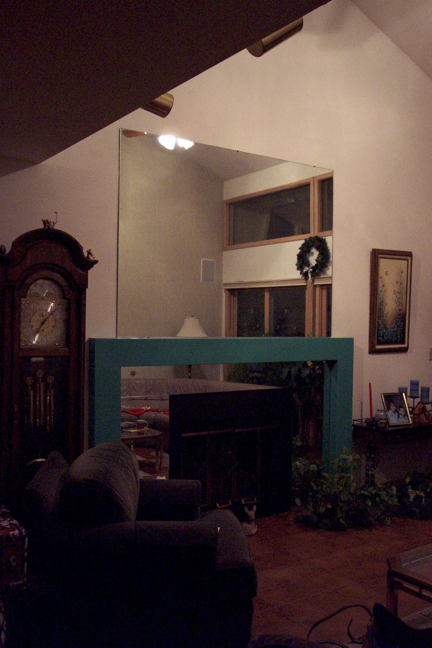
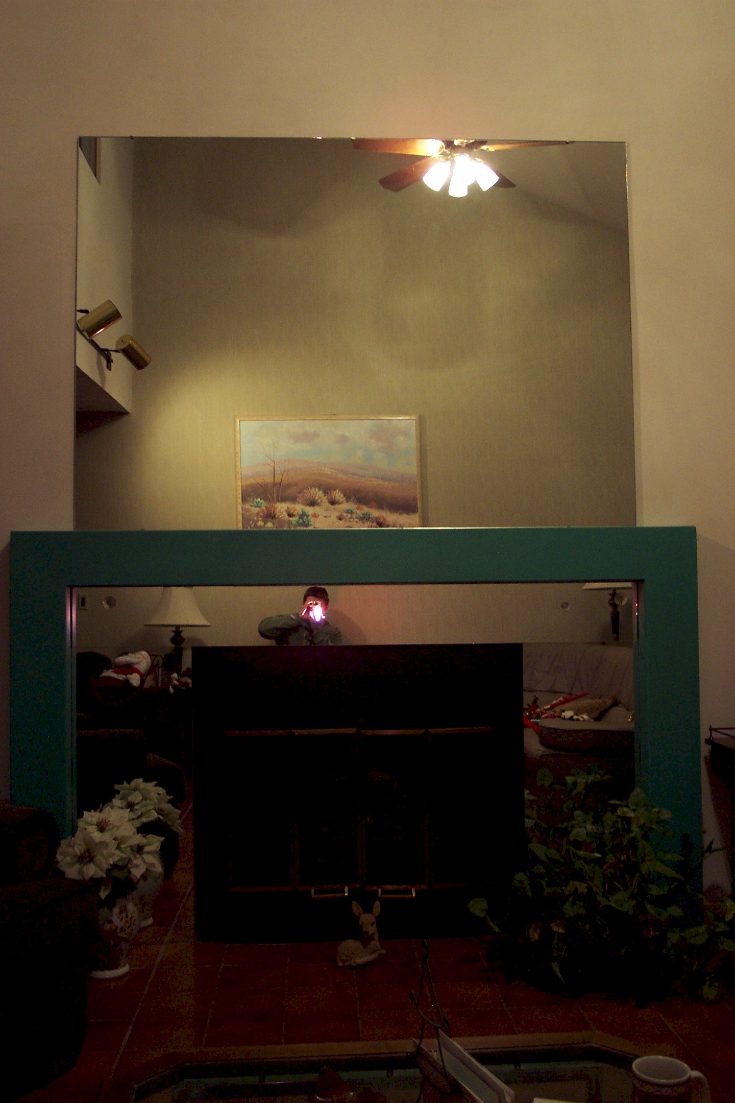
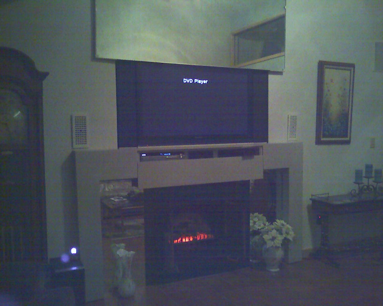
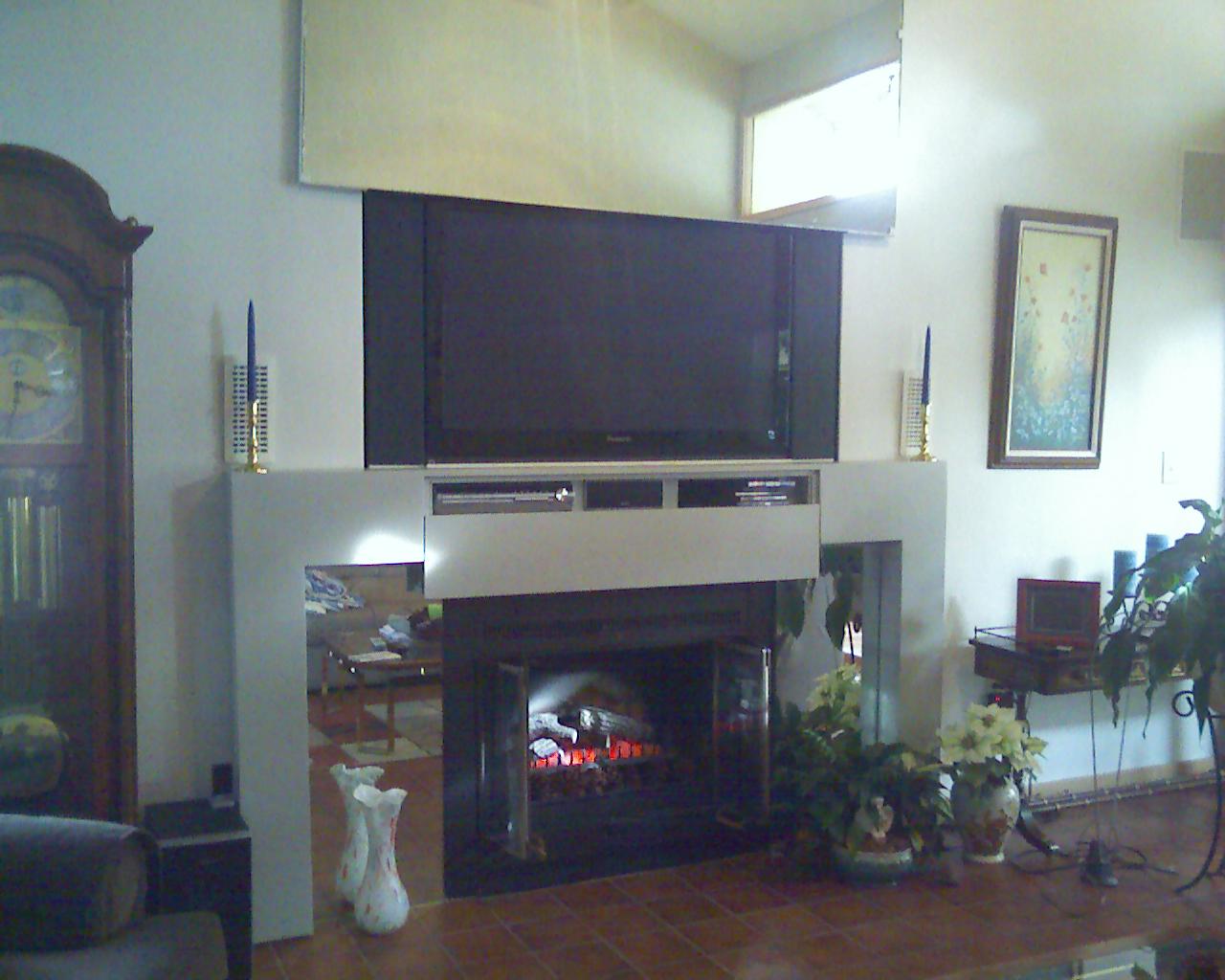
Pictures eight, nine, and ten depict the final form of the mantle, mirror configuration, and rear speaker placement.
|
|
| Broken Mirror Redesign | 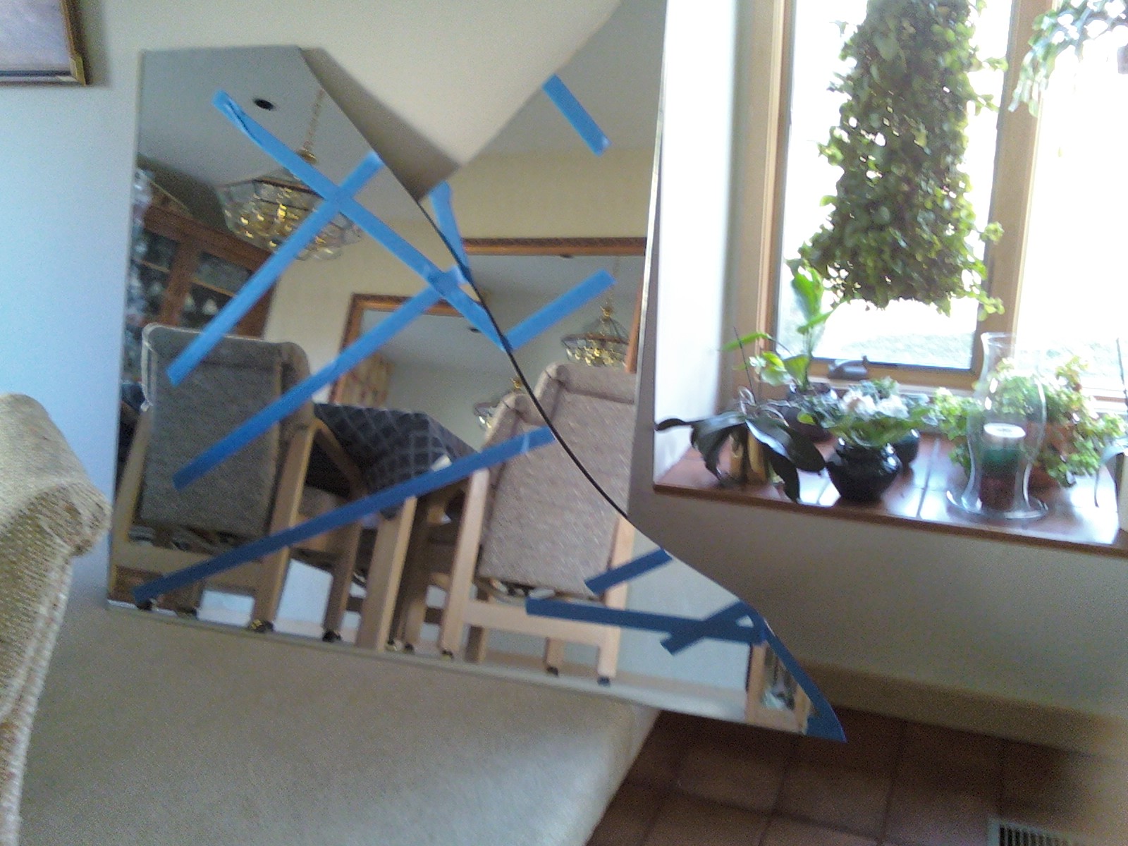
|
|
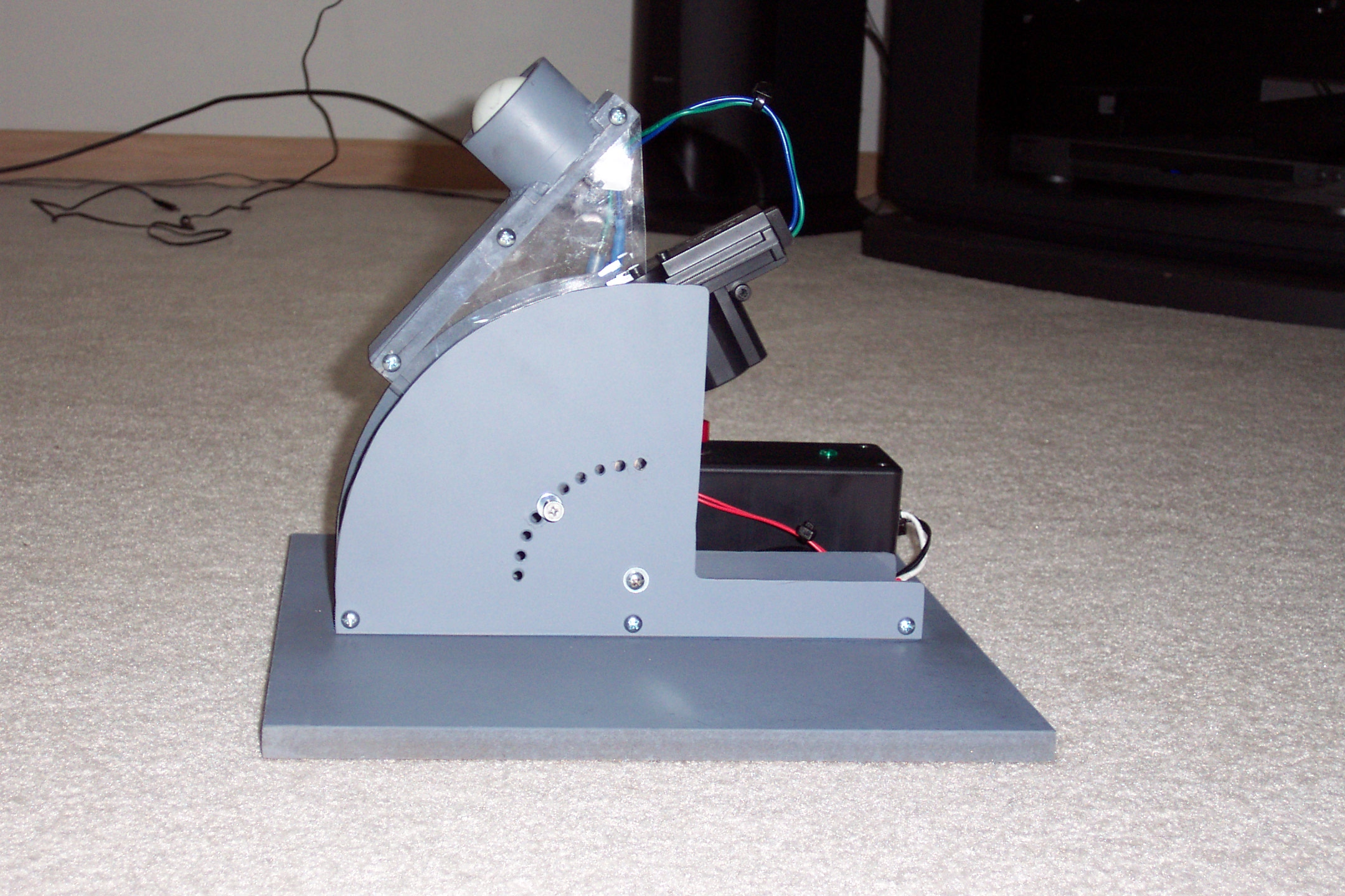
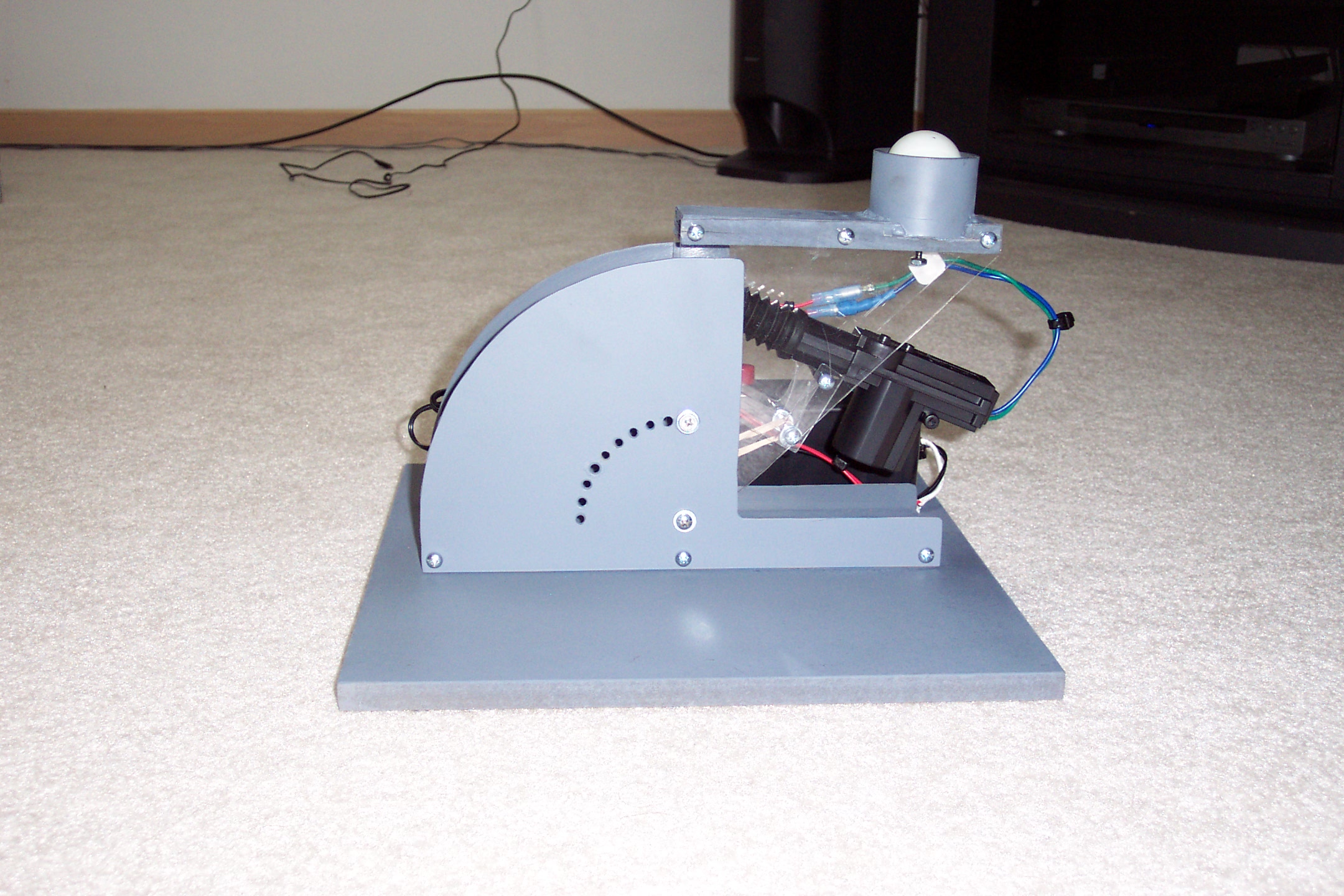
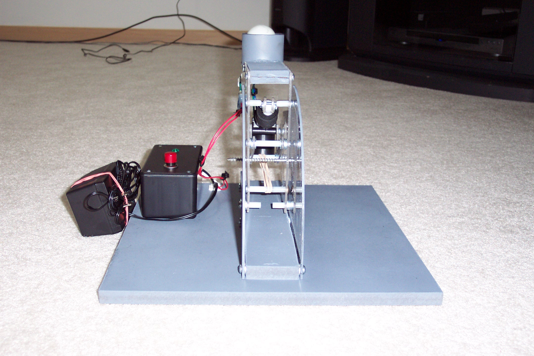
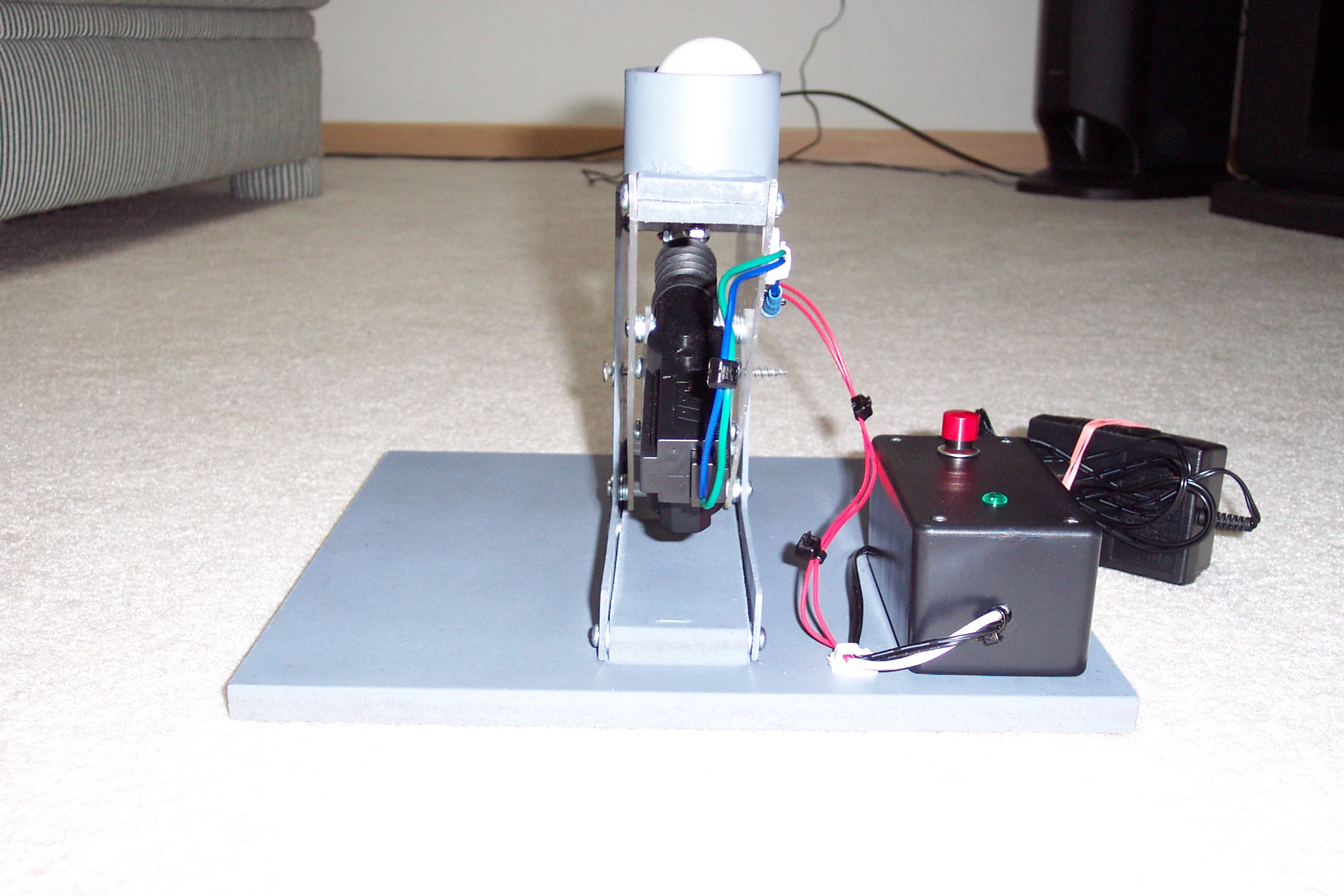
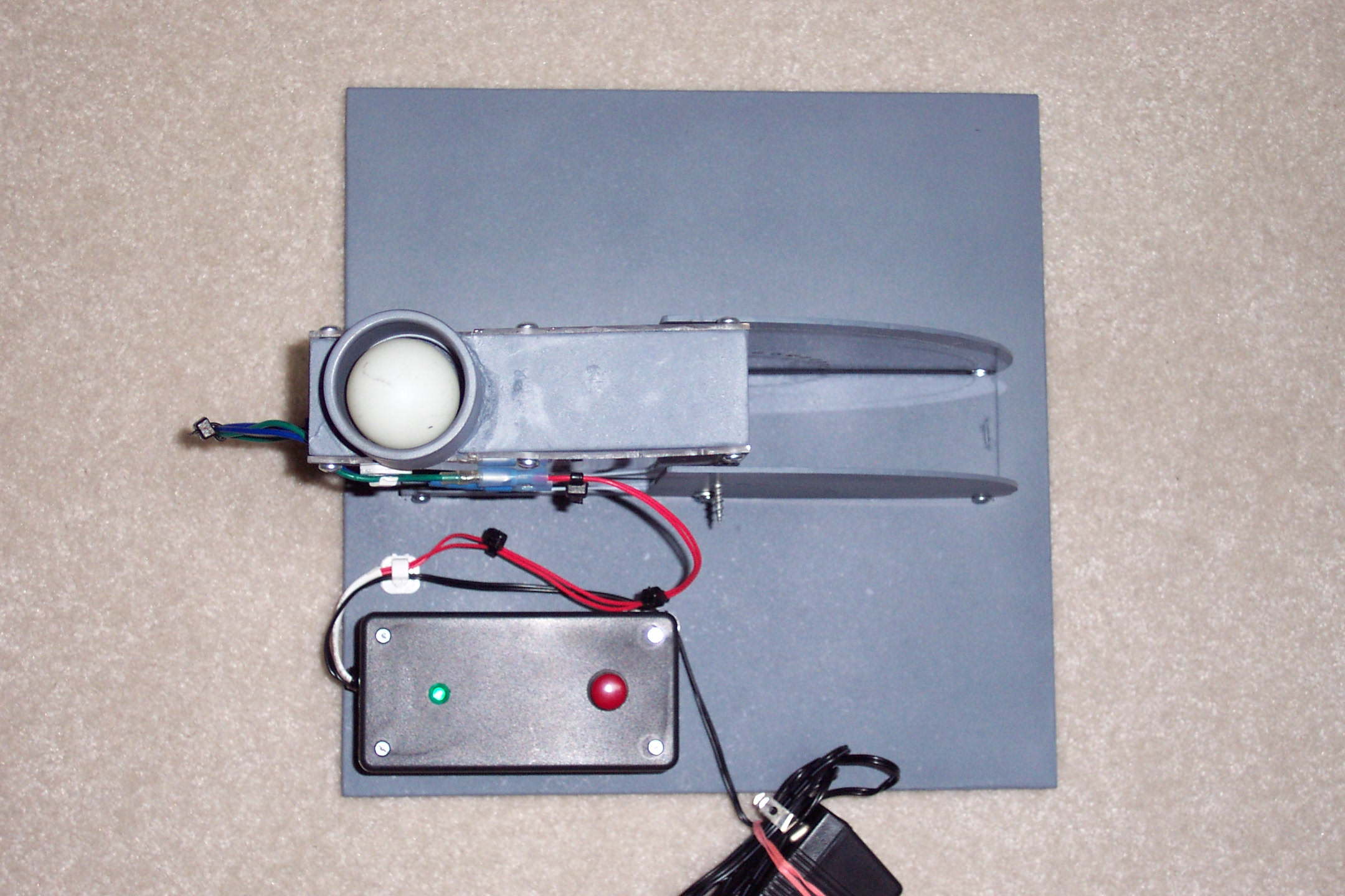
Ping
Pong Ball Projectile Device
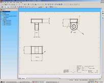
The midterm test, of a SolidWorks class at Requirement of the design included the repeatable propulsion of a ball from a desired 0º to 90º. I decided to configure the device around the use of an automotive 12 volt door lock actuator and a converter. The completed design was chosen to be presented to the physics department as a tool and project for education. The four pictures below depicts the personal fabricated demonstration version of the propulsion device.
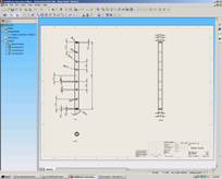
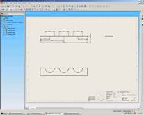
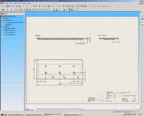
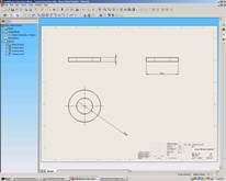
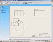
The following pictures show some of the SolidWorks drawing required for the project design and fabrication.
|
|
|
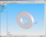
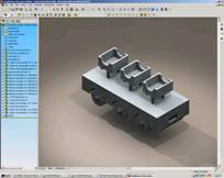
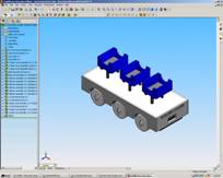
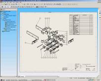
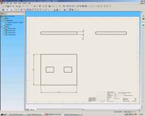
Children’s Toy Utilizing Cams SolidWorks final project required the students to design and fabricate a children’s toy utilizing cams for motion of some type. The instructor informed the students to reference the duck toy that raises and lowers its head while rolling it along the floor. I chose to fabricate a roller coaster with three cars that raise and lower in a connected fashion. The attachments below provide drawings of all of the parts and a rendition of the finial roller coaster toy.
|
|
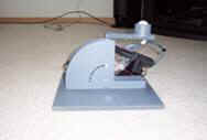
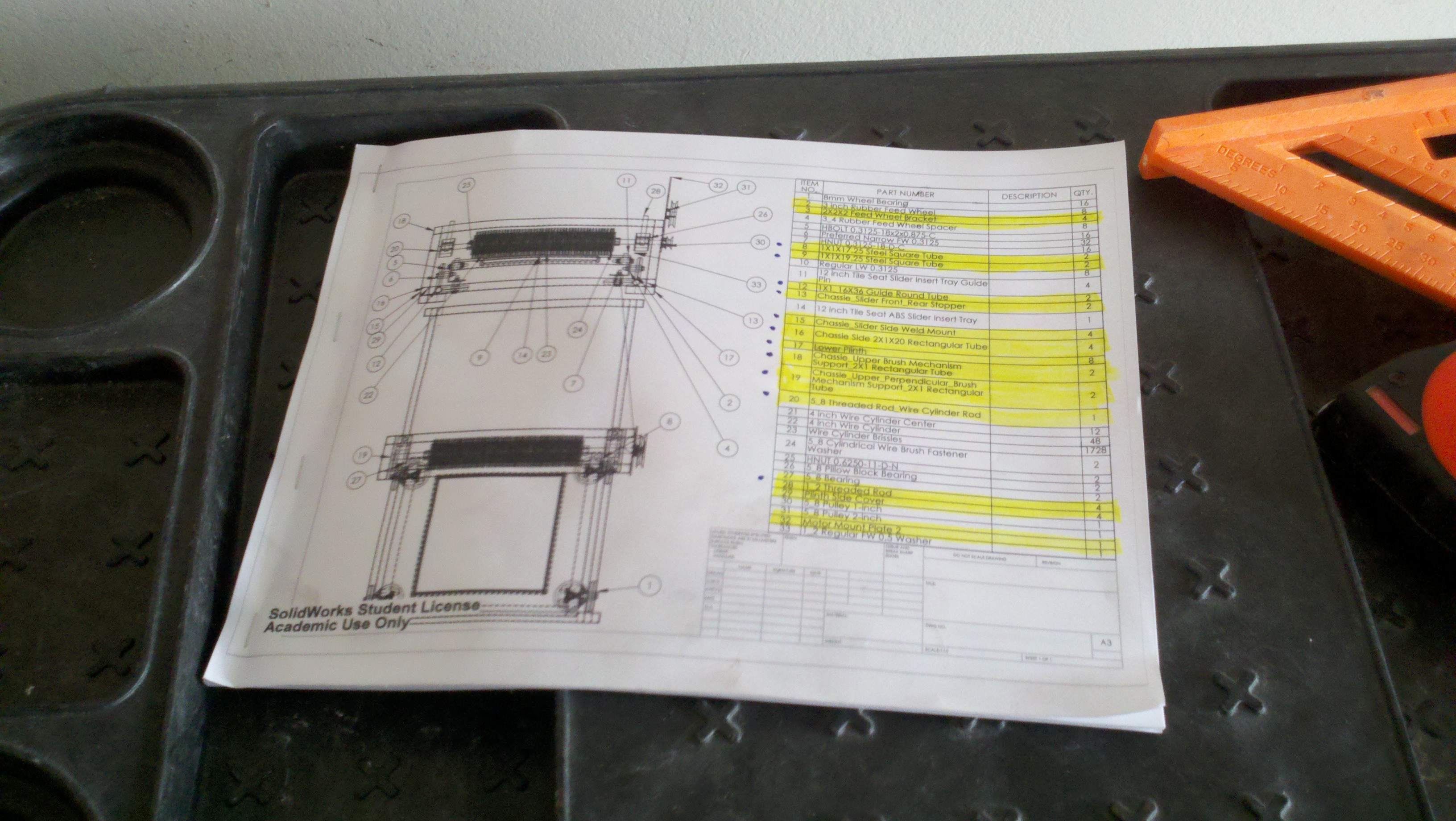
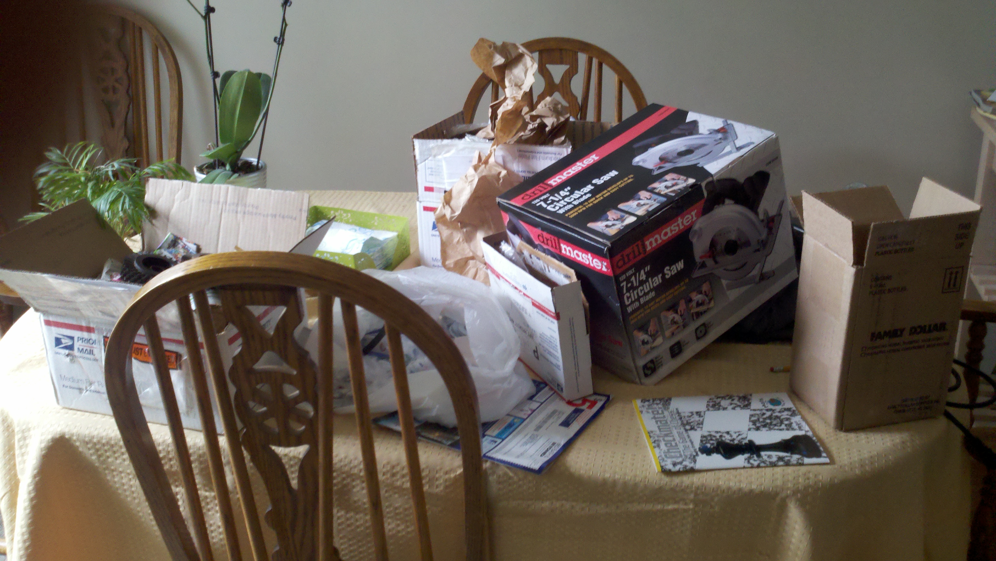
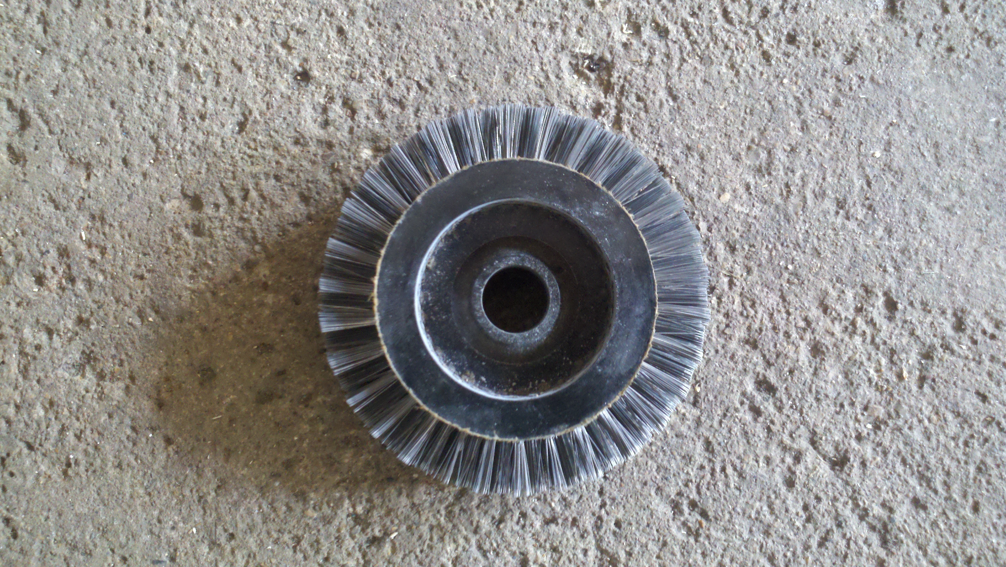
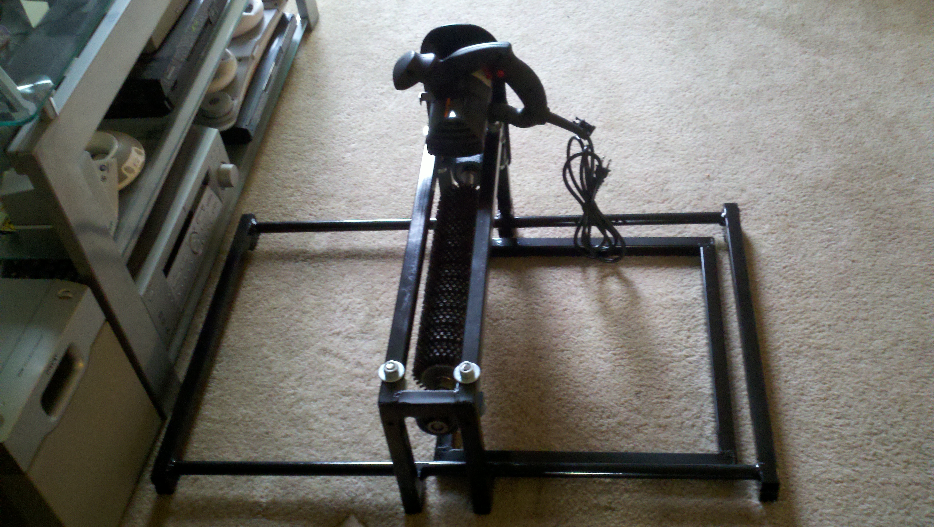
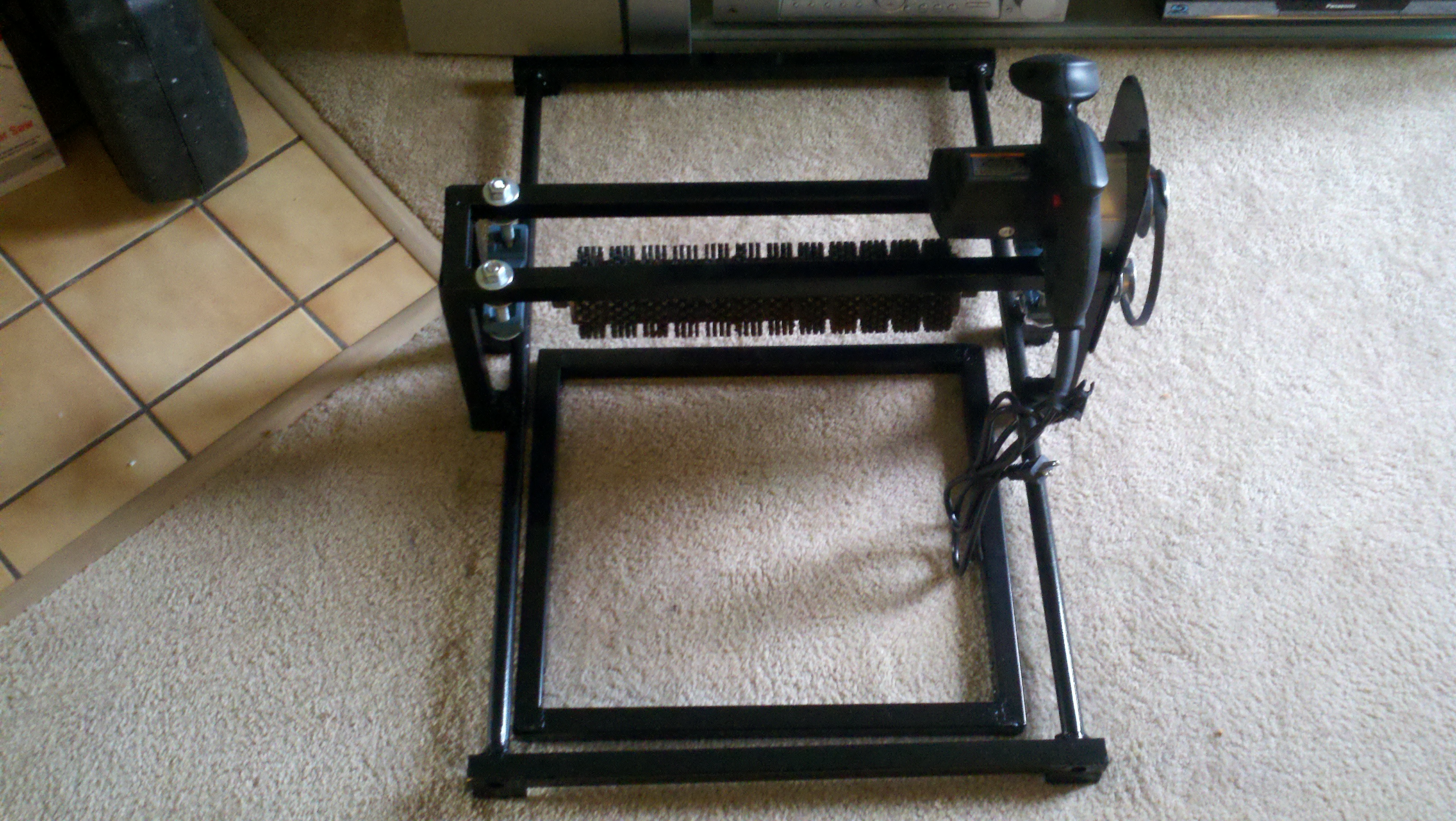
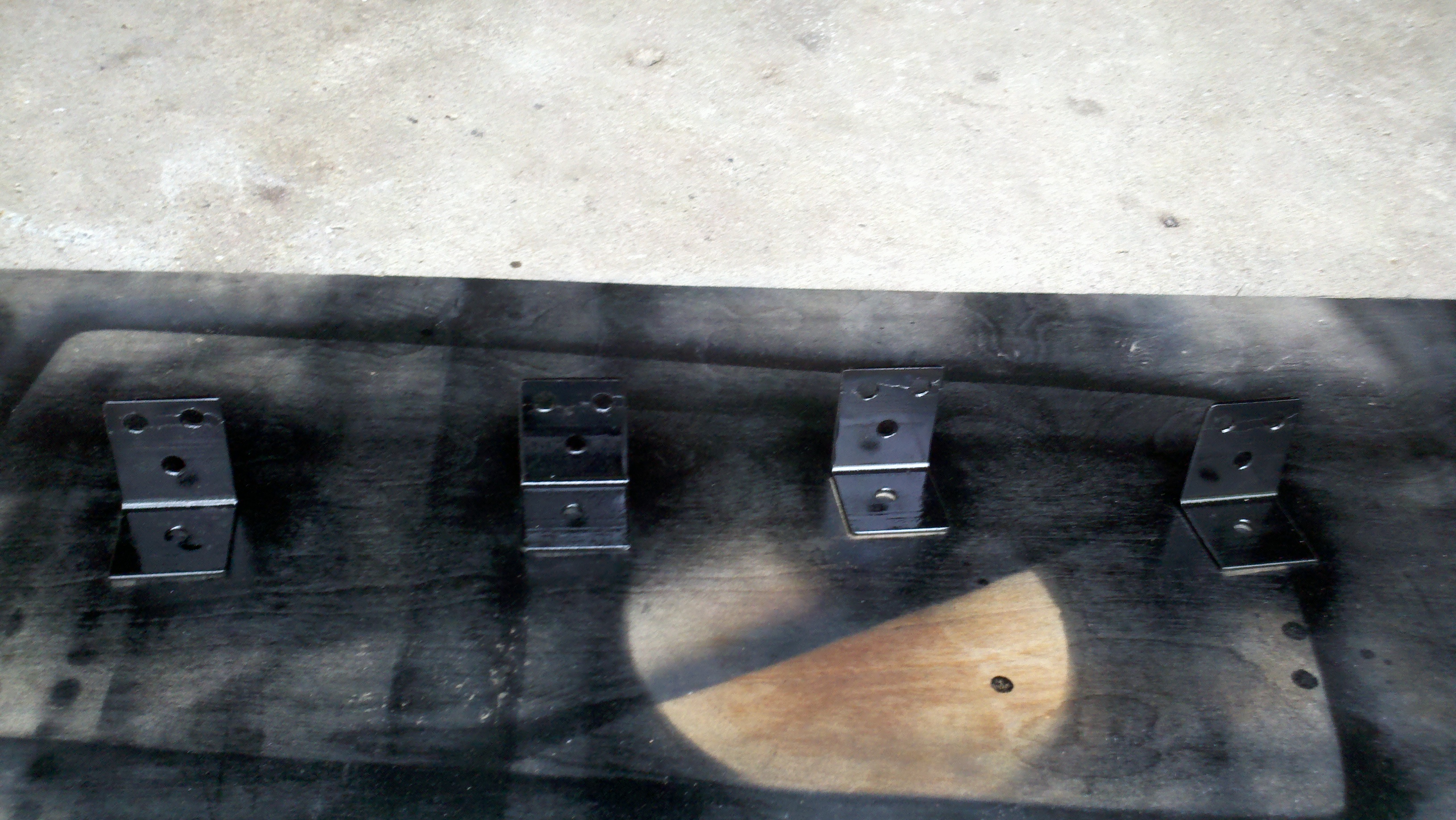
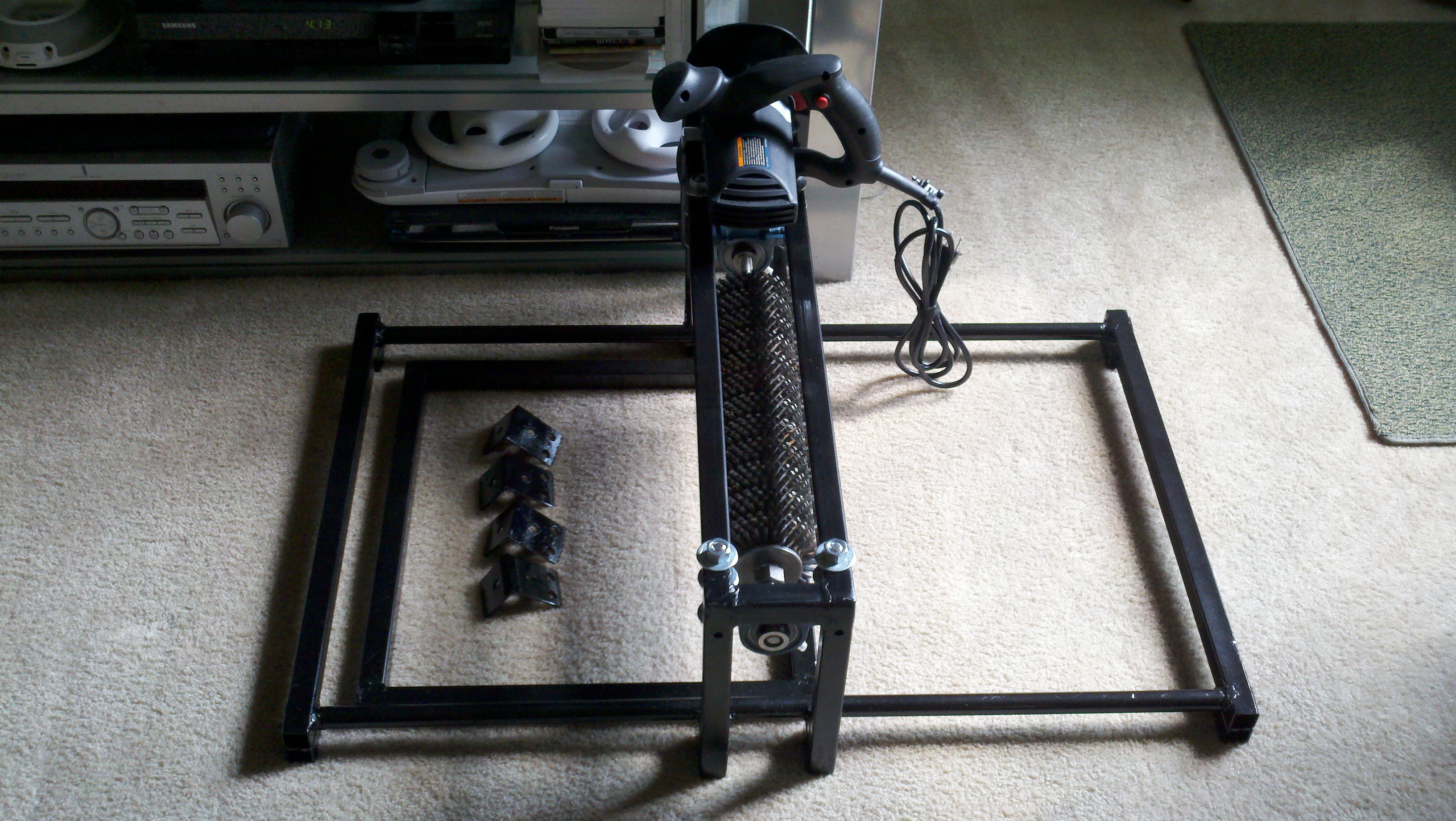
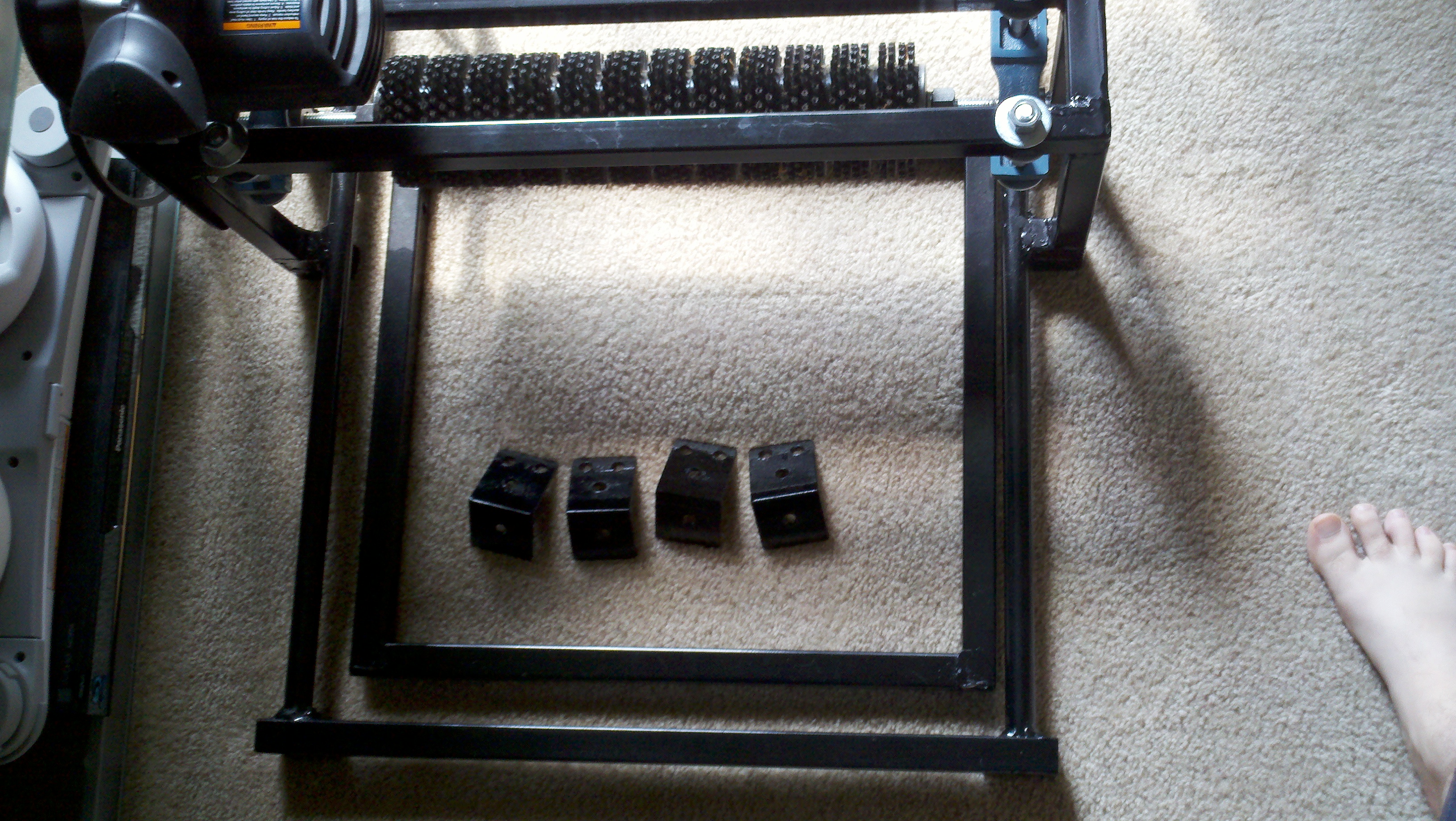
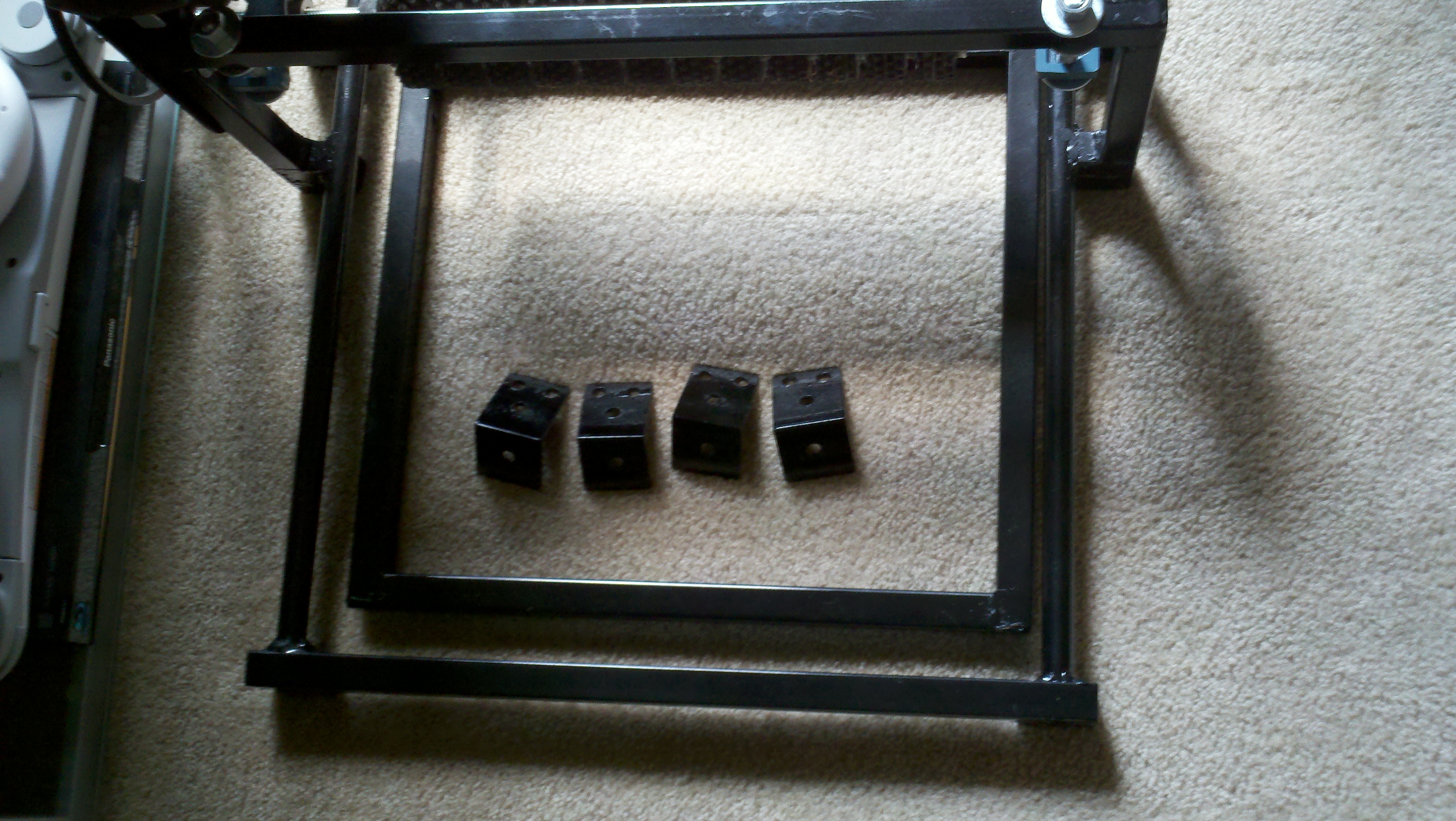
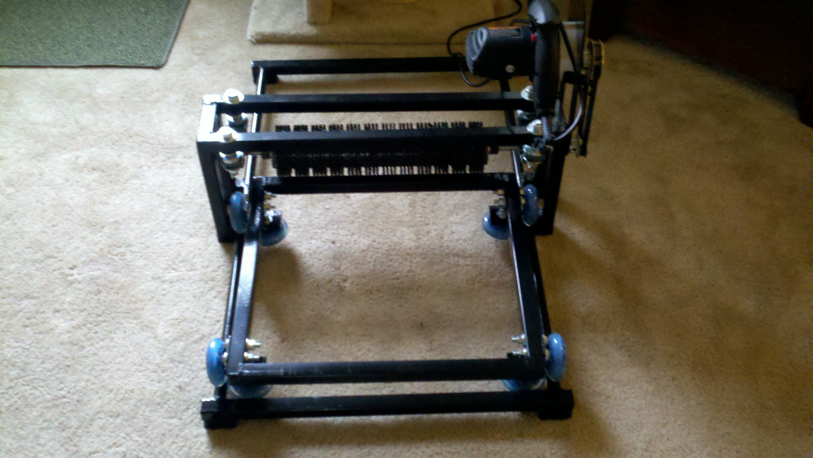
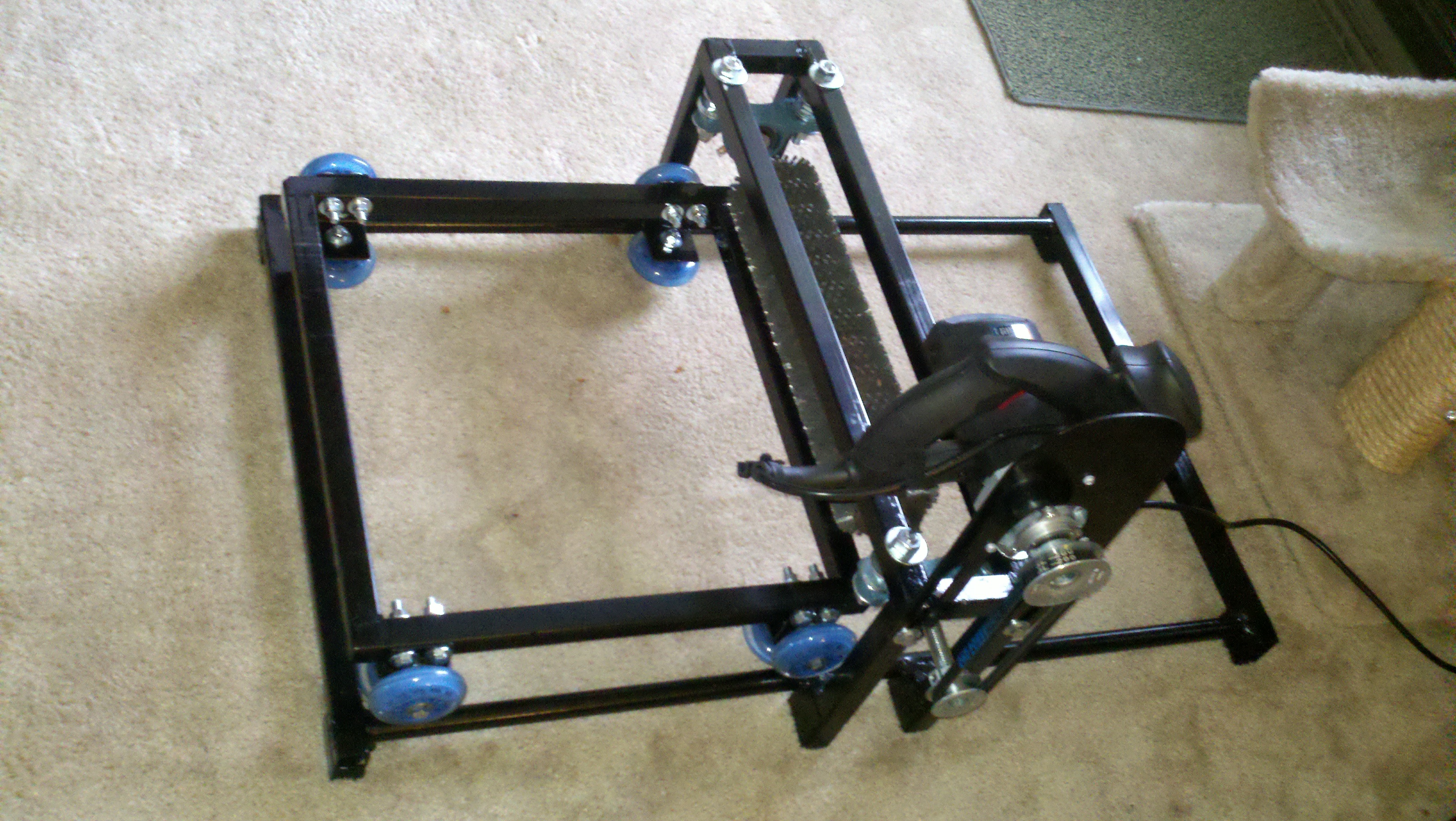
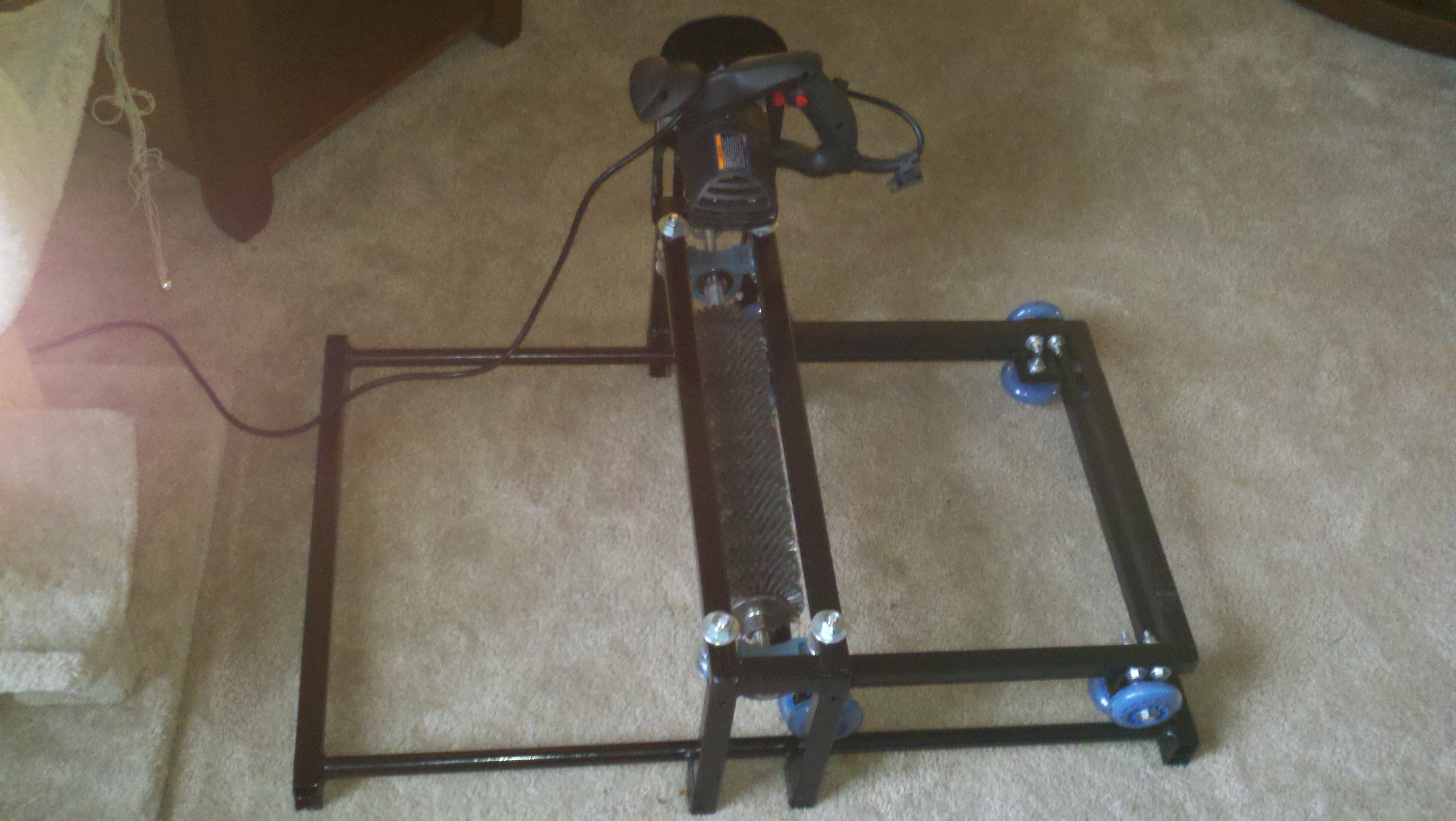
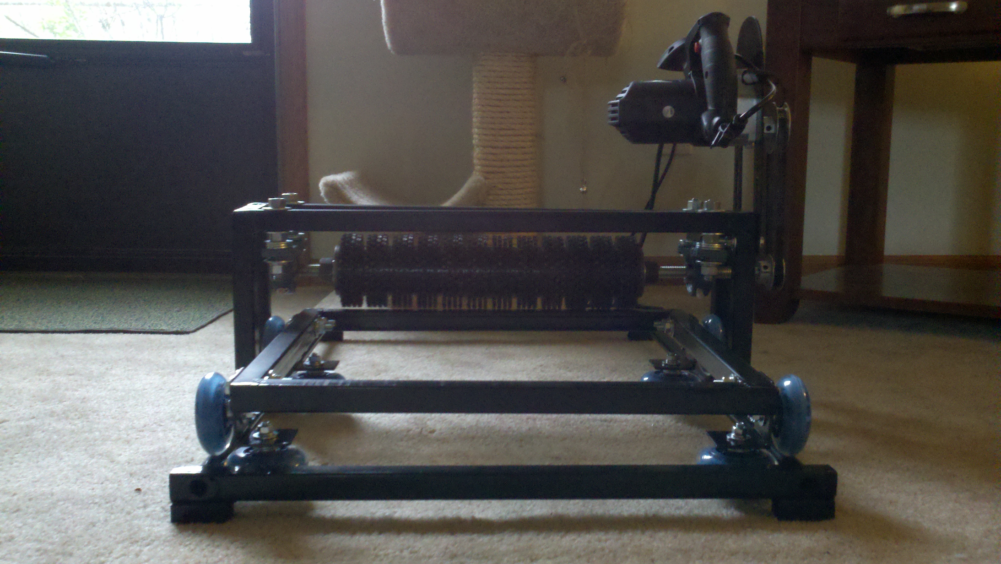
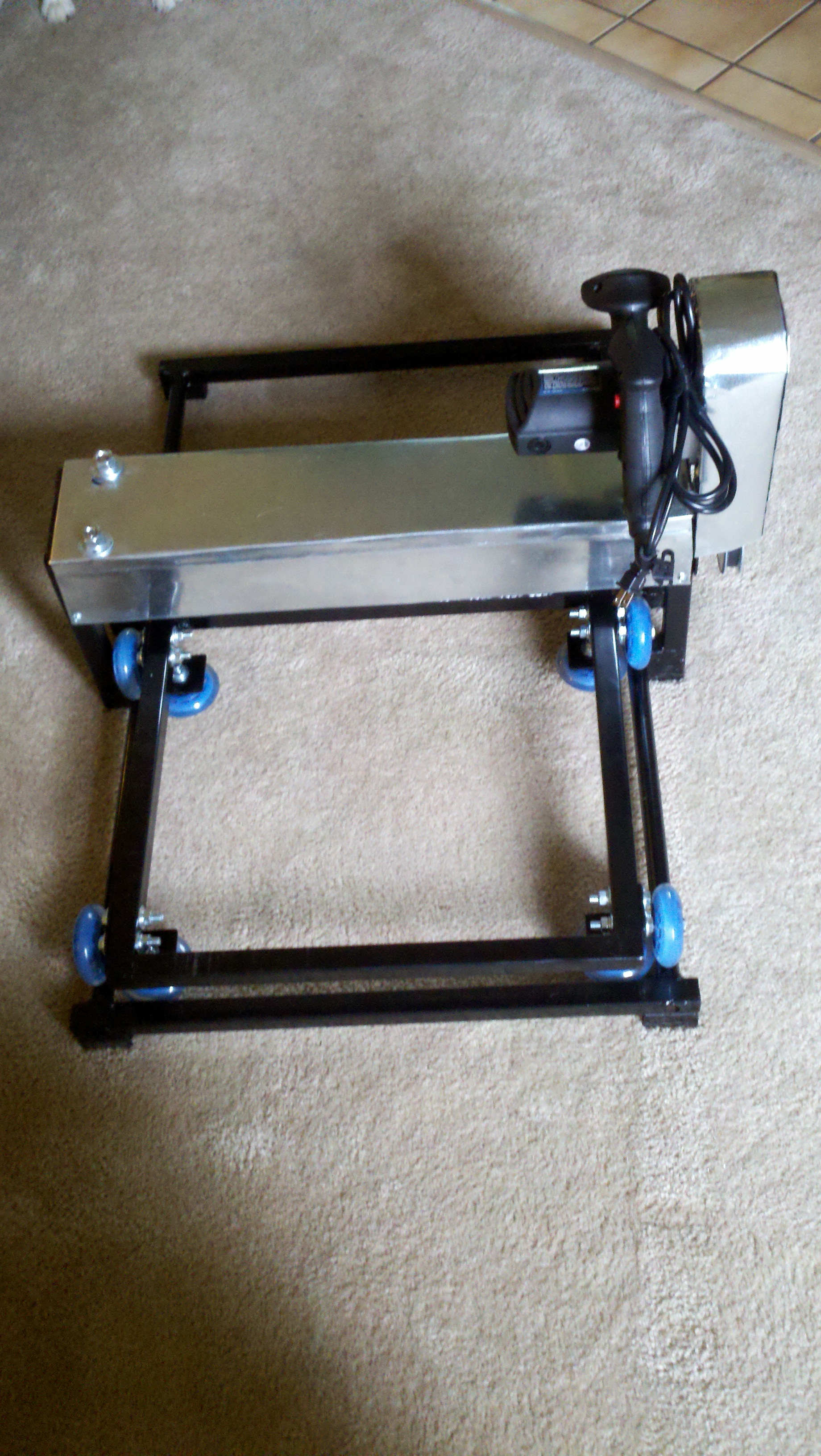
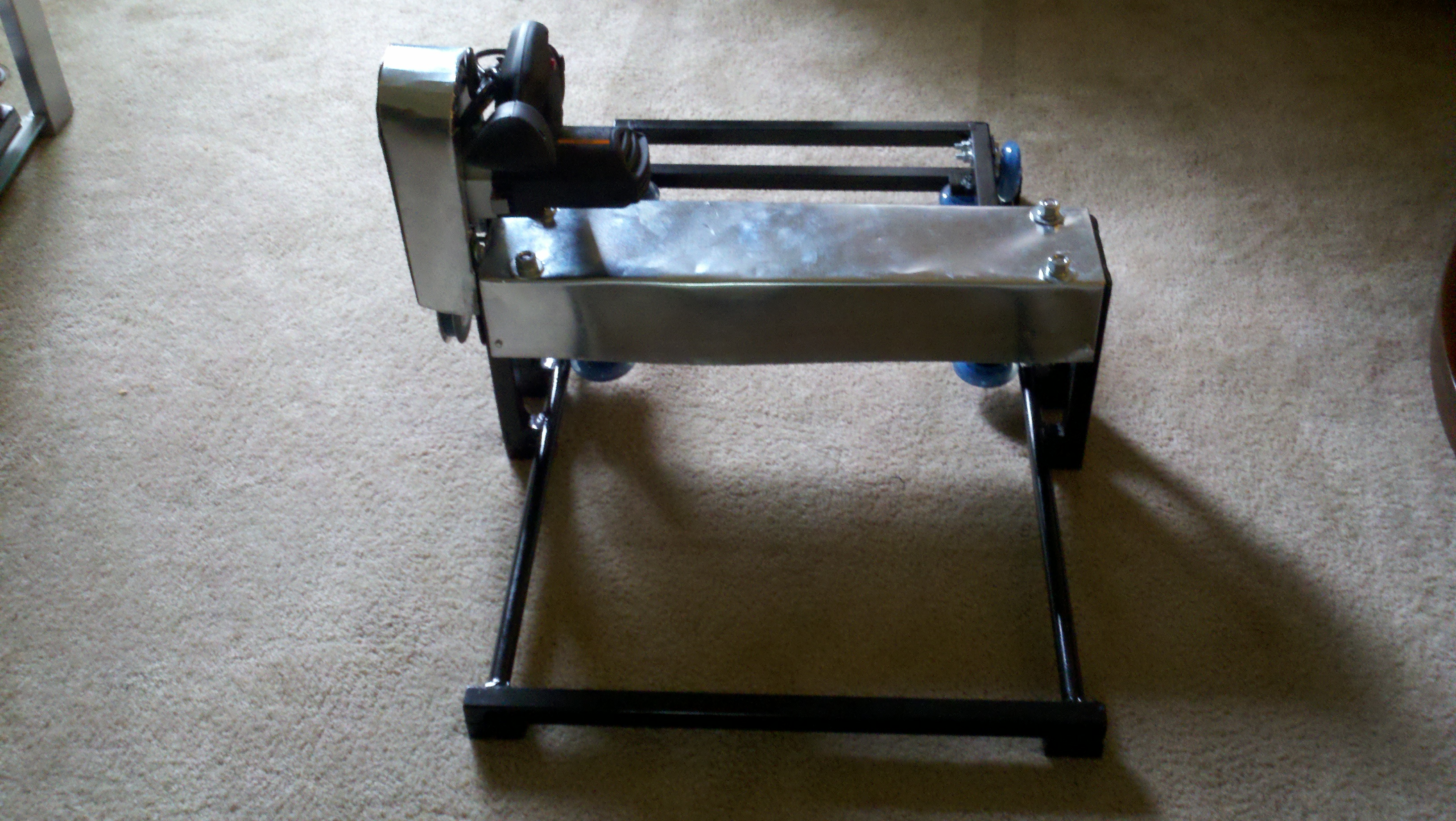
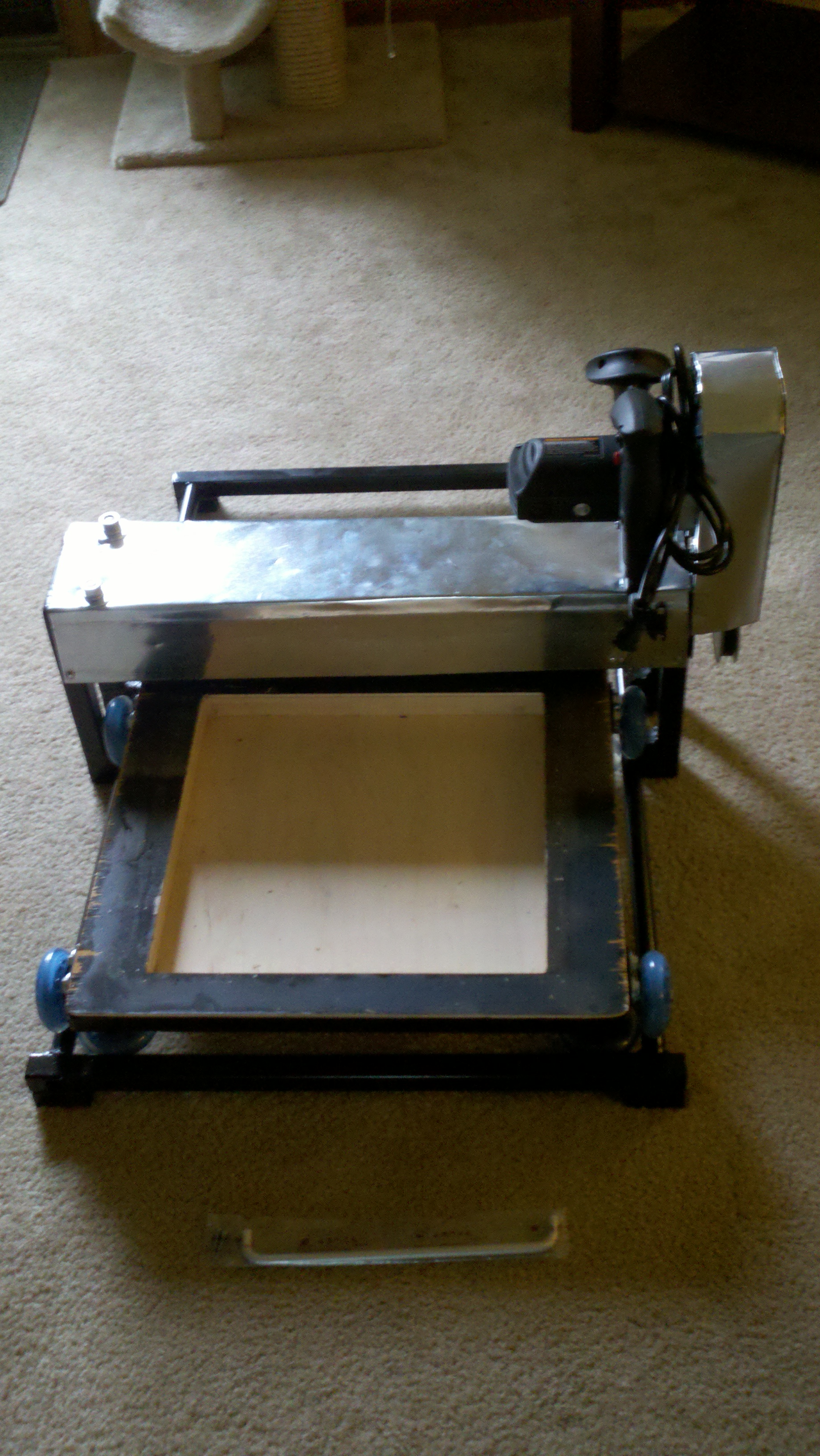
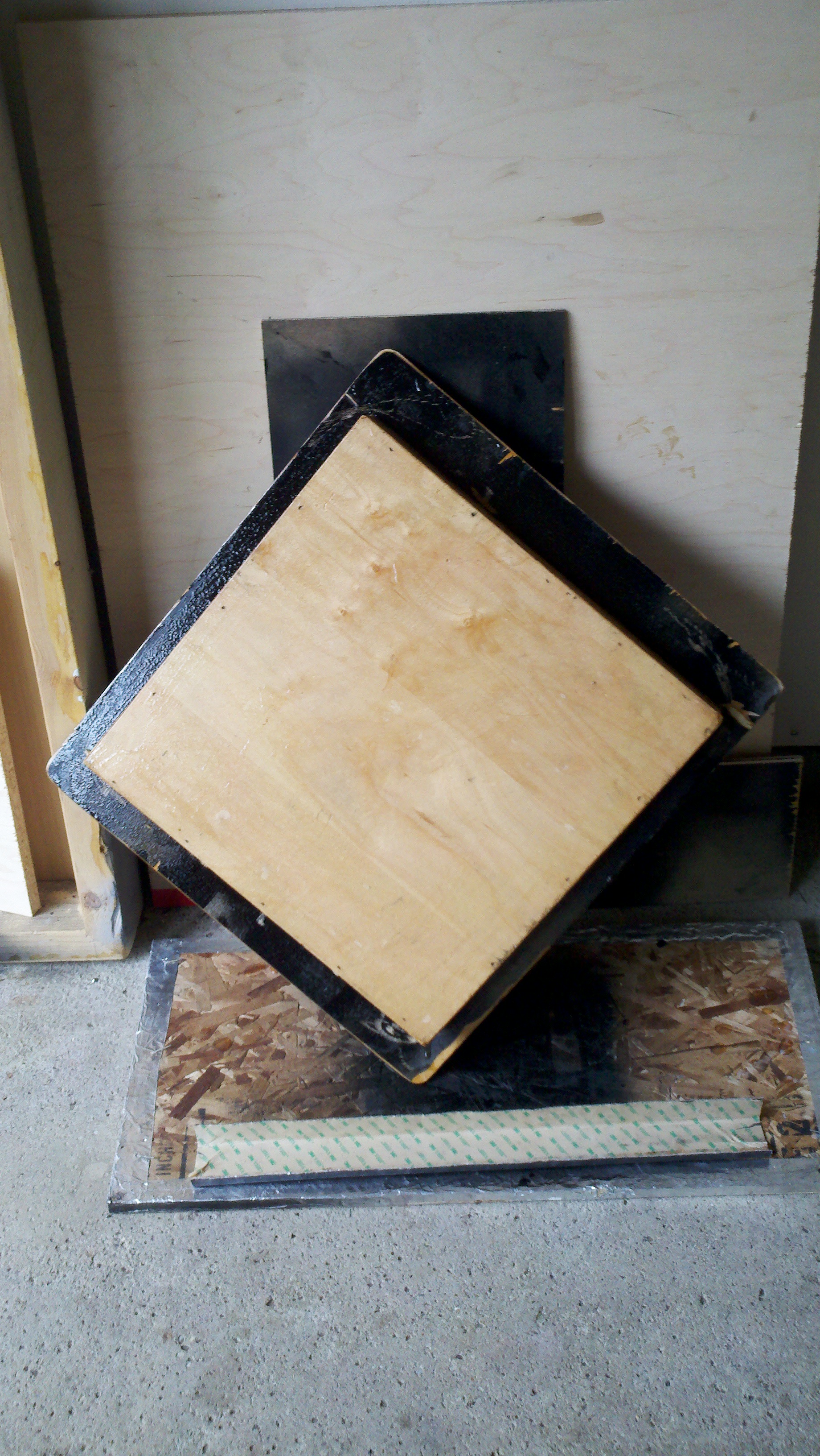
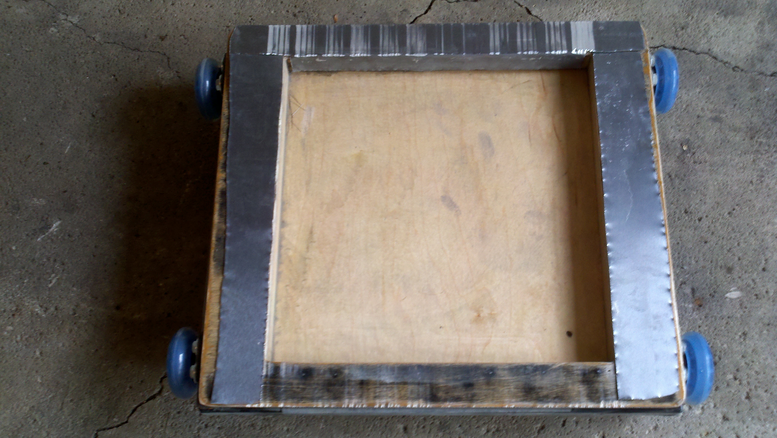
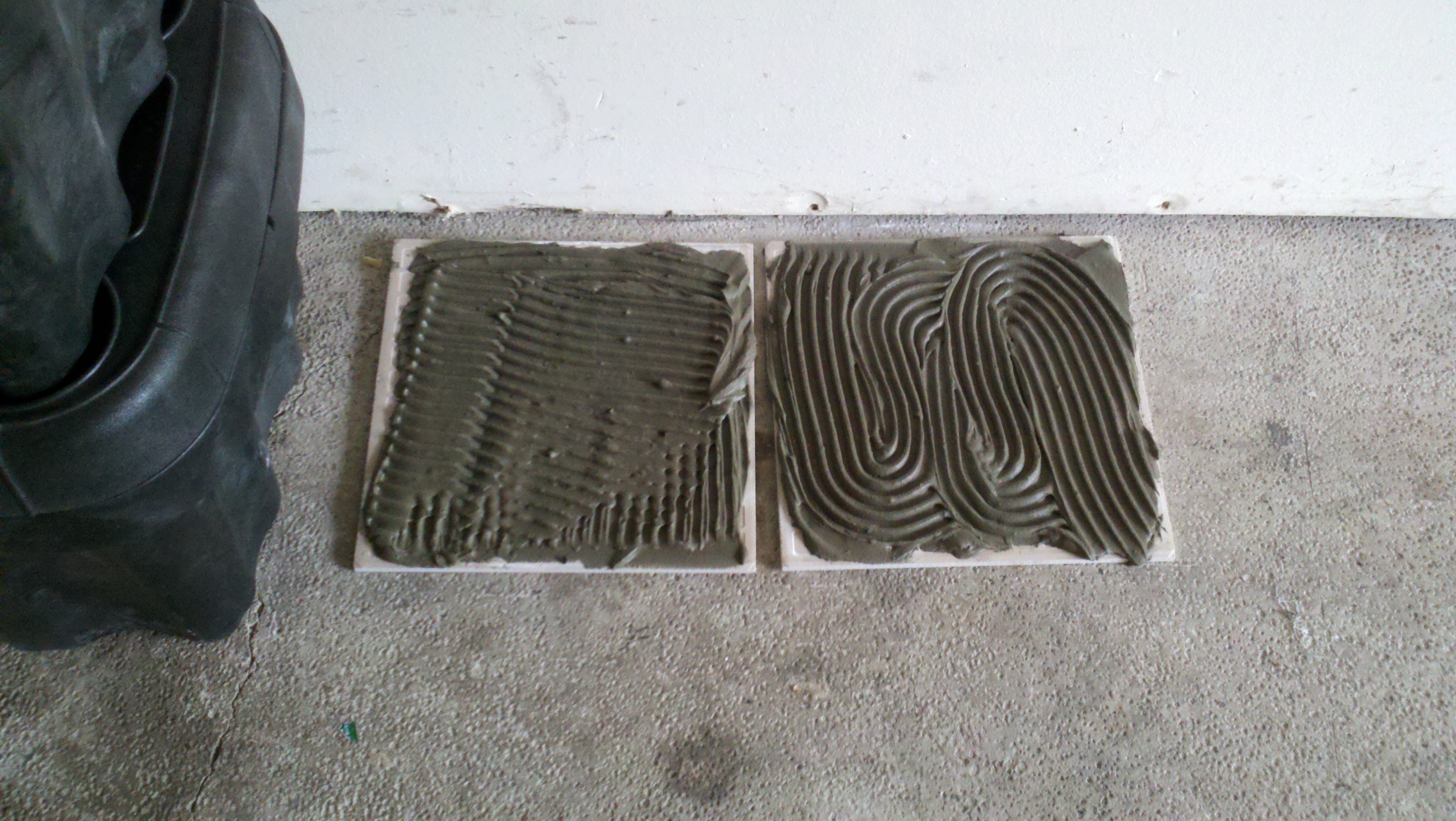
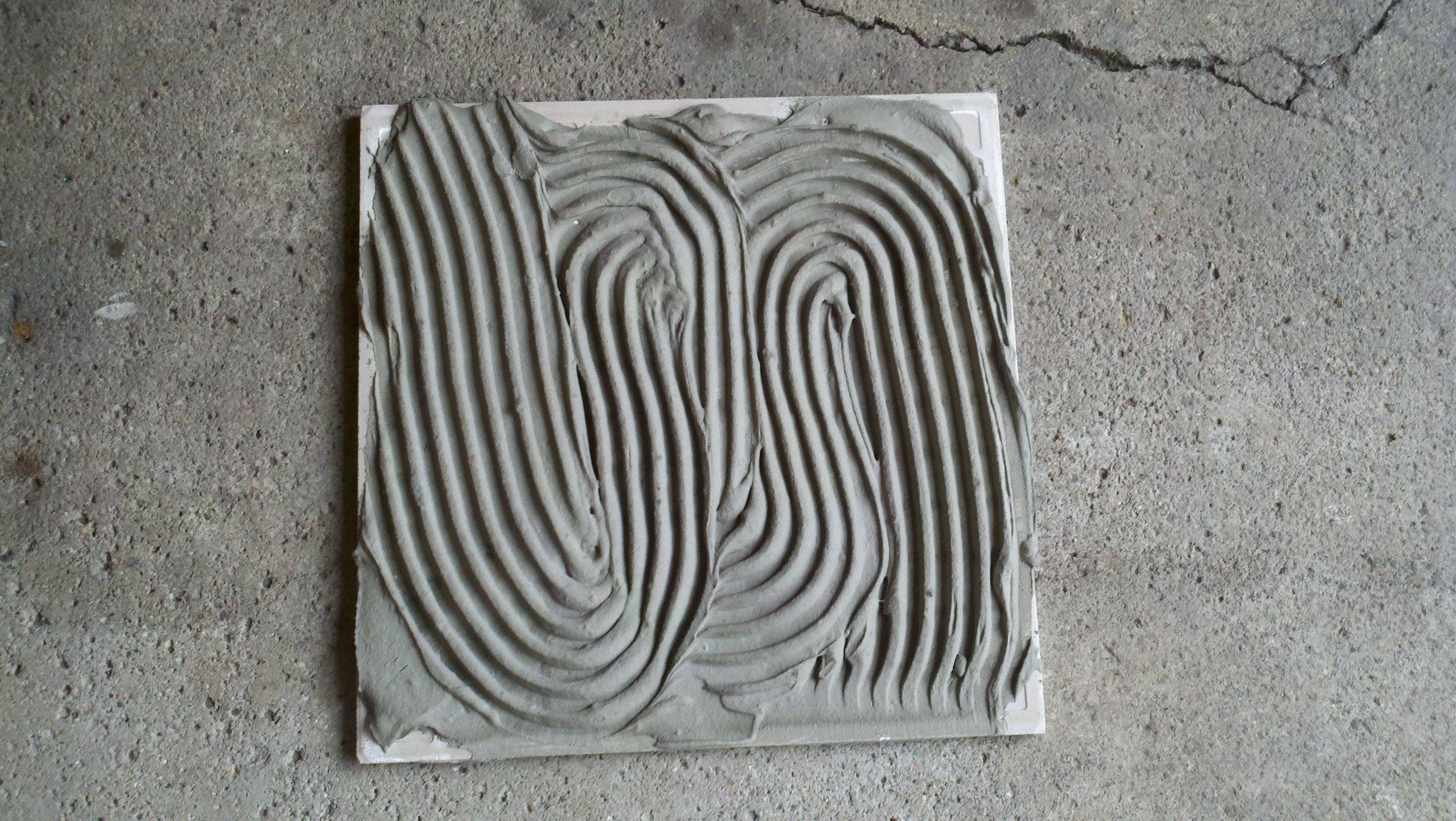
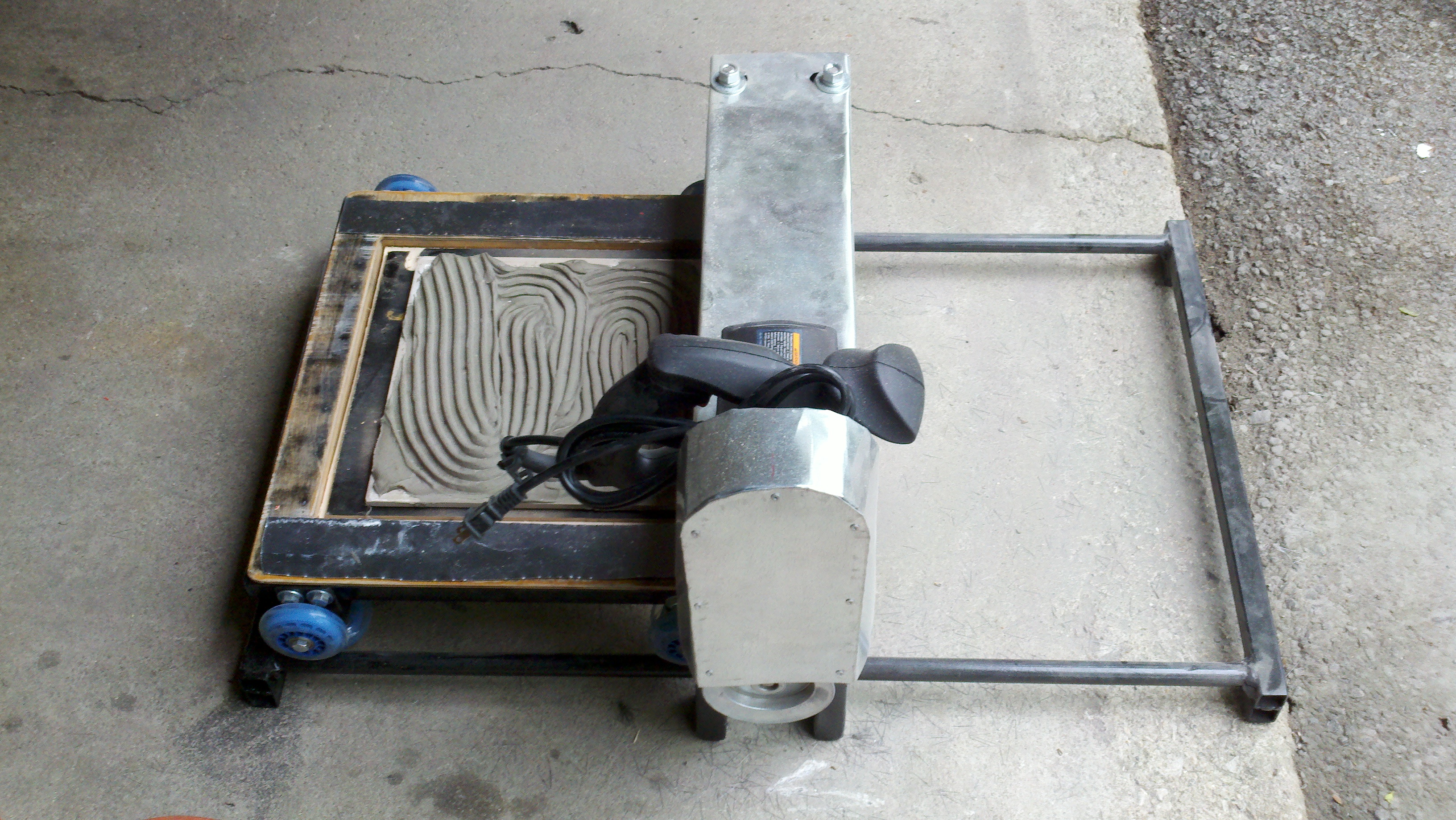
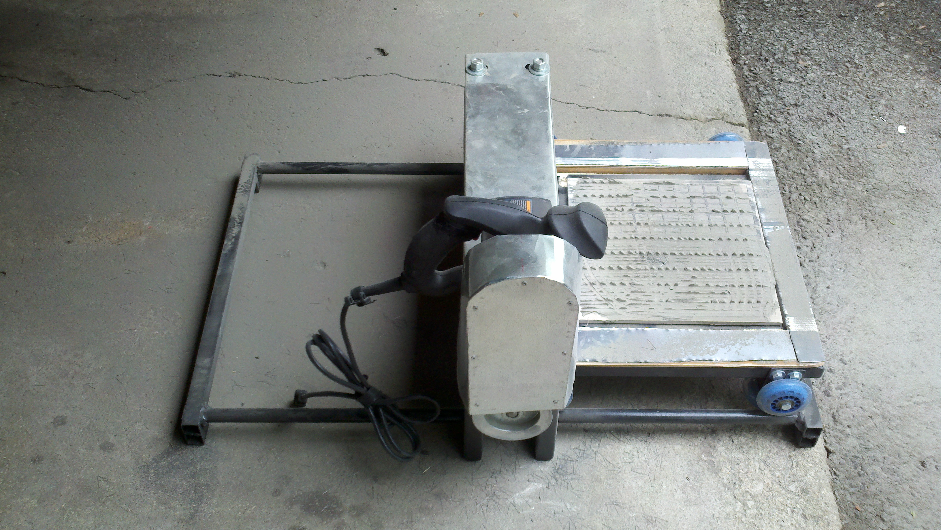
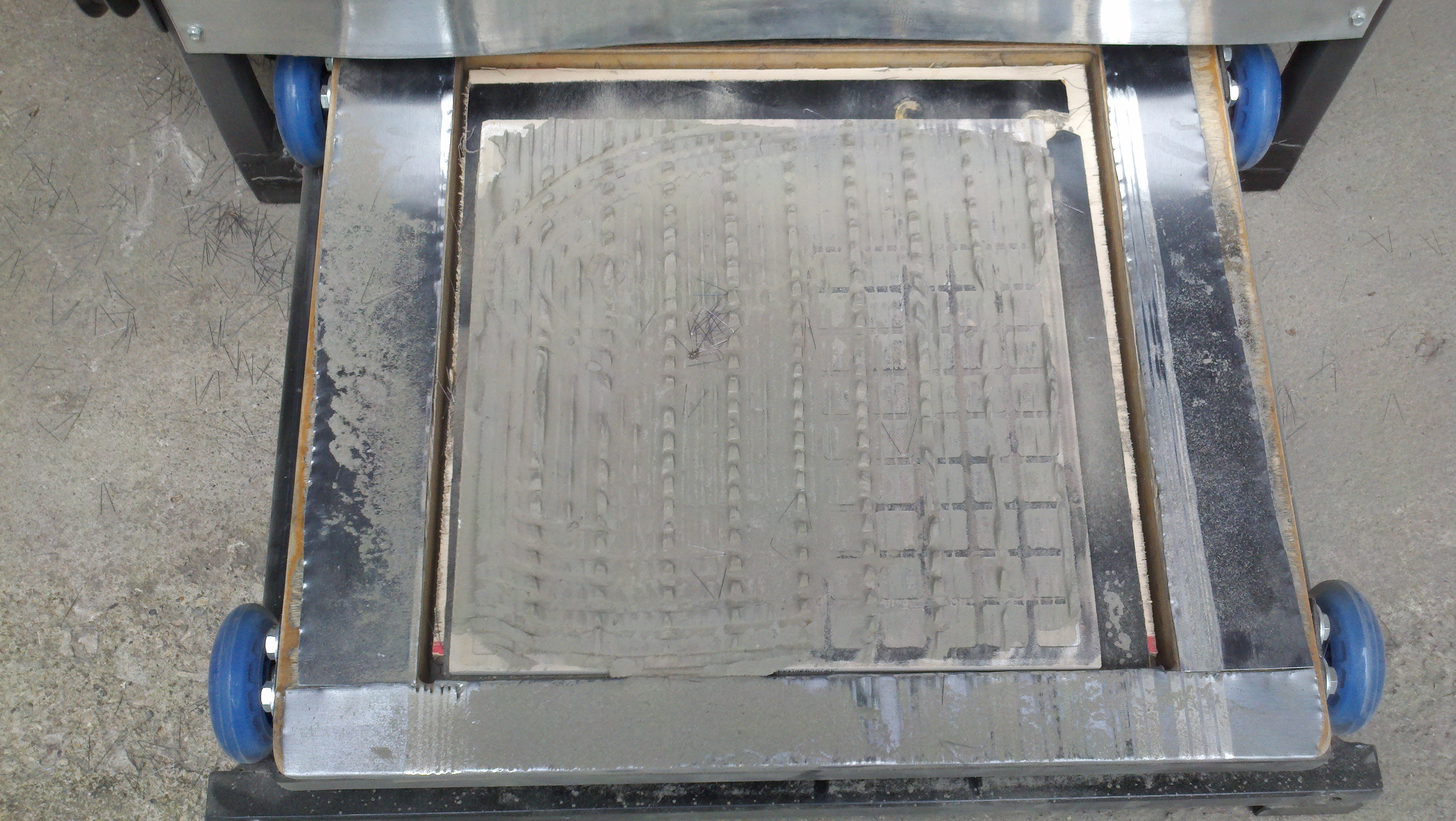
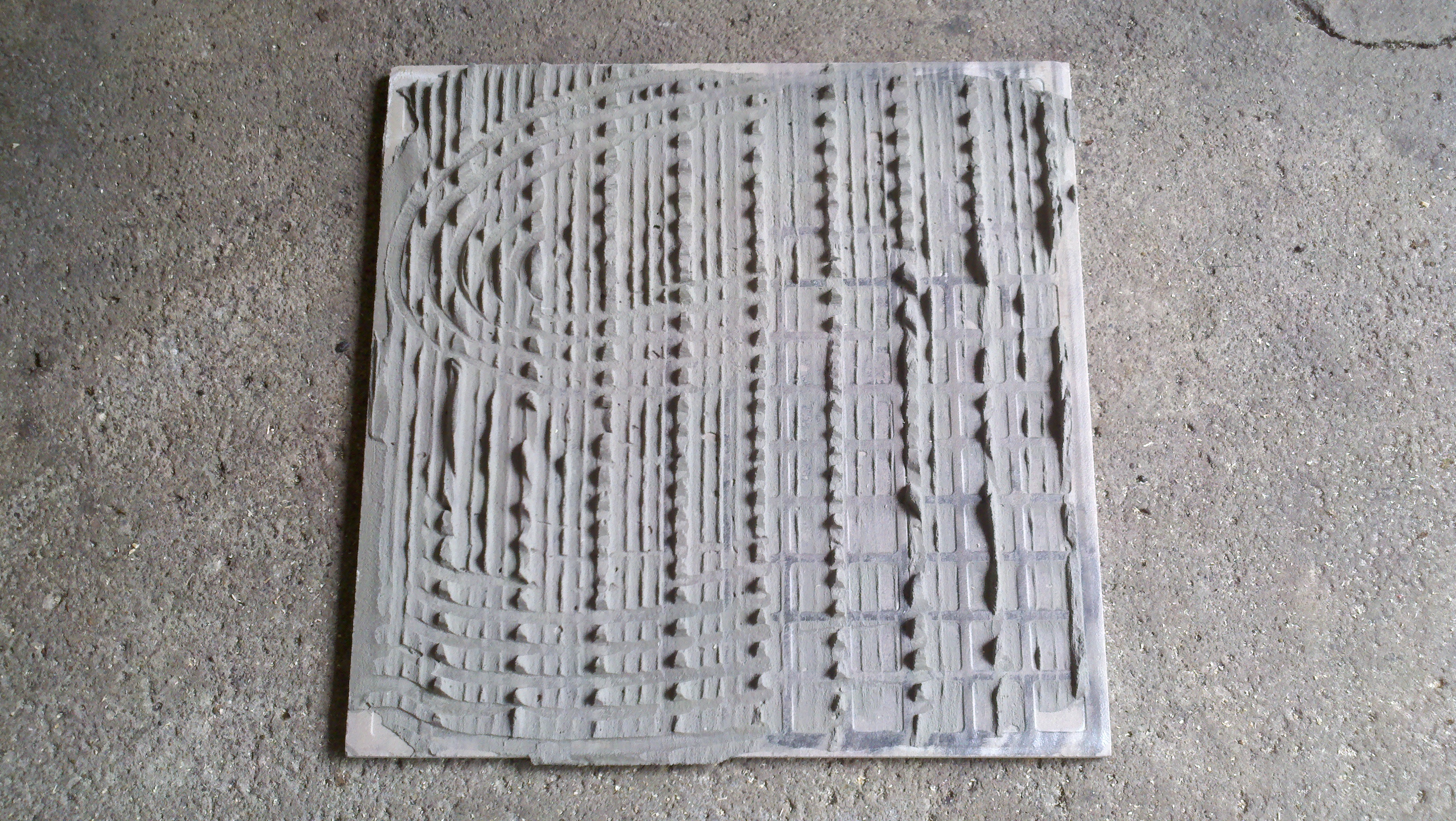
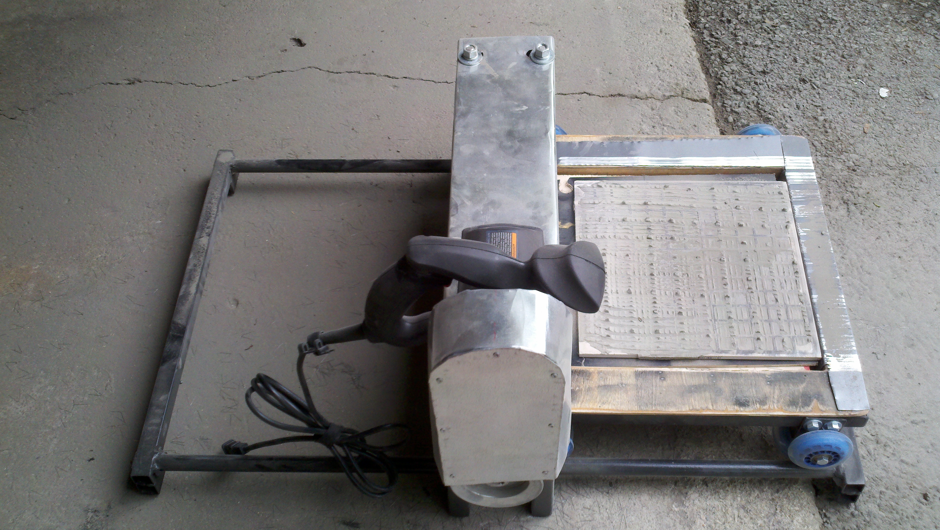
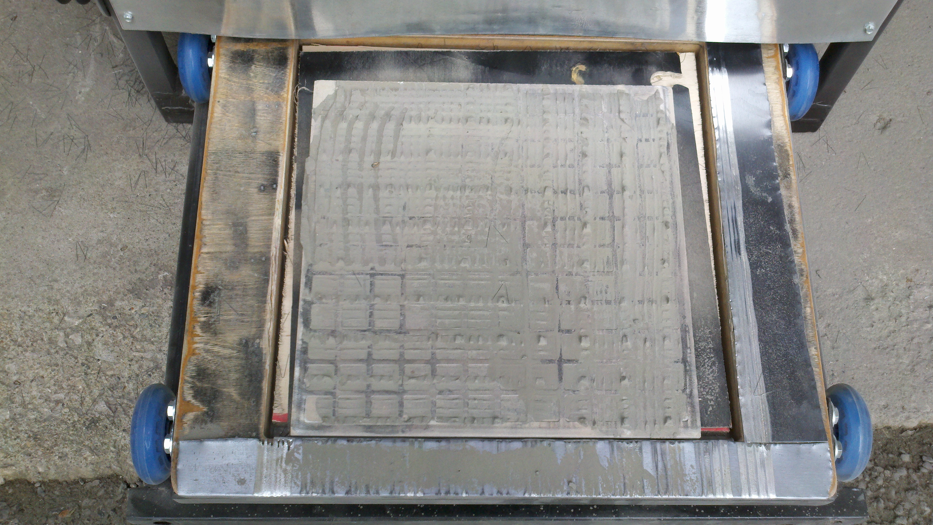
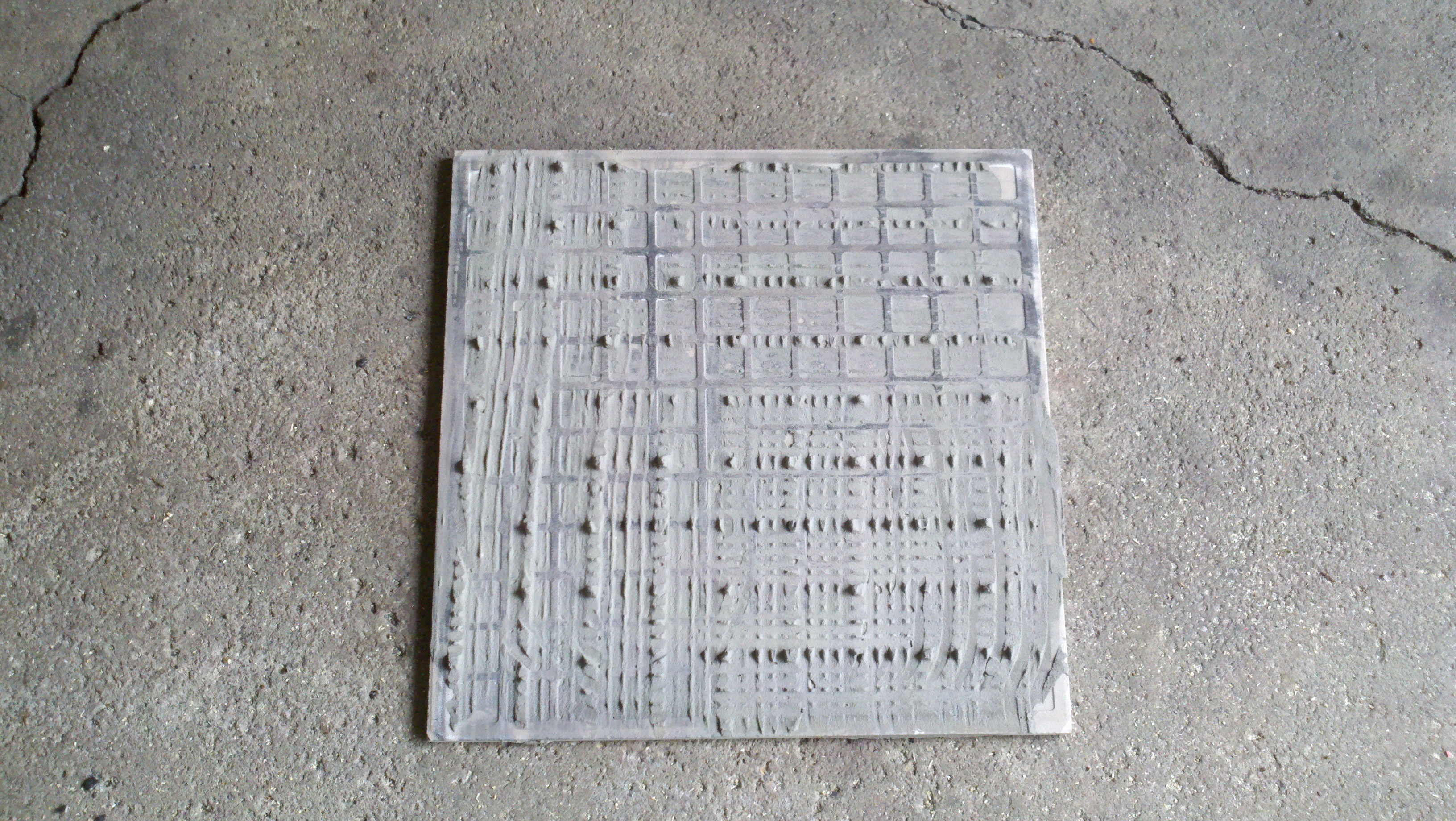
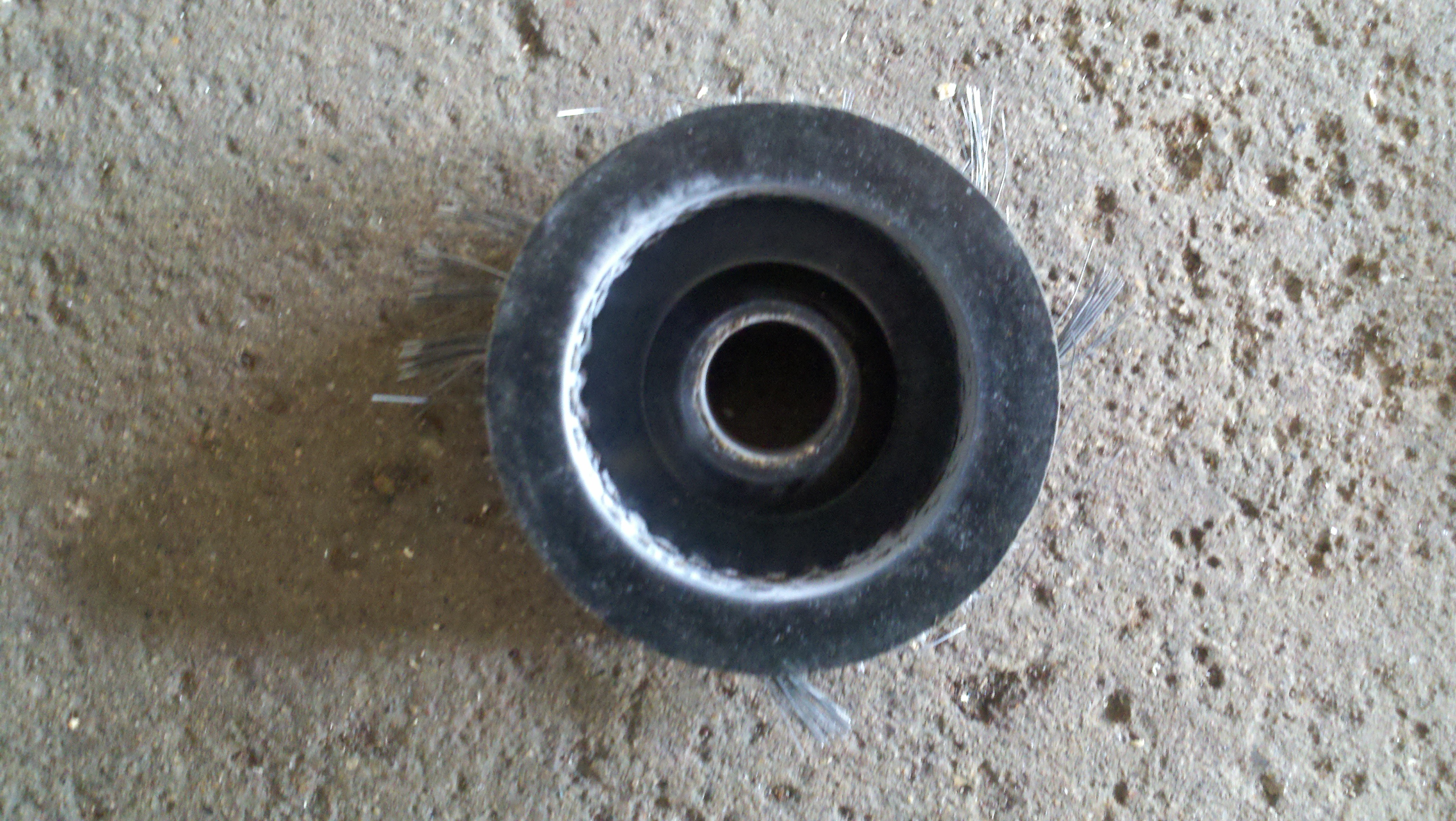
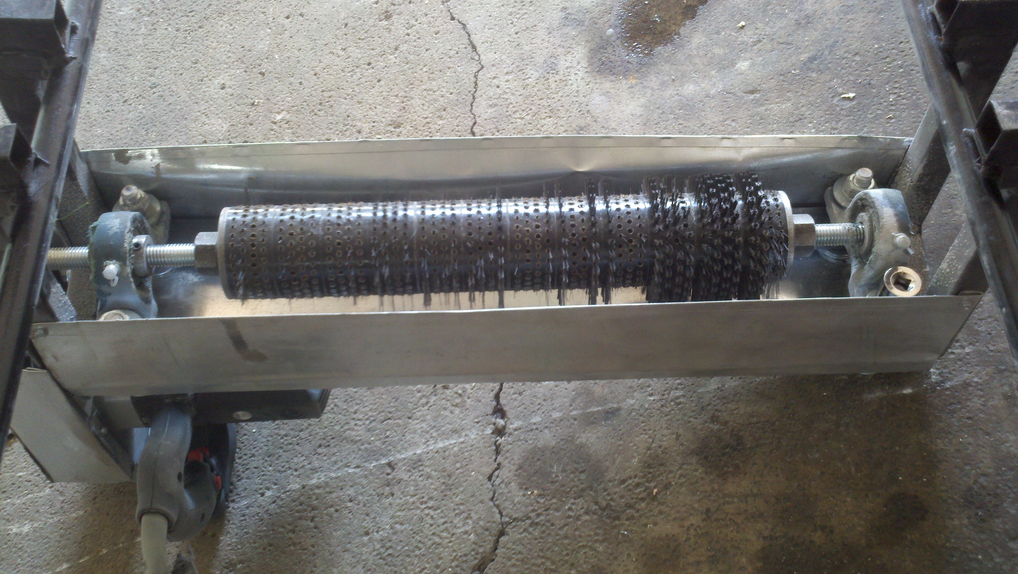
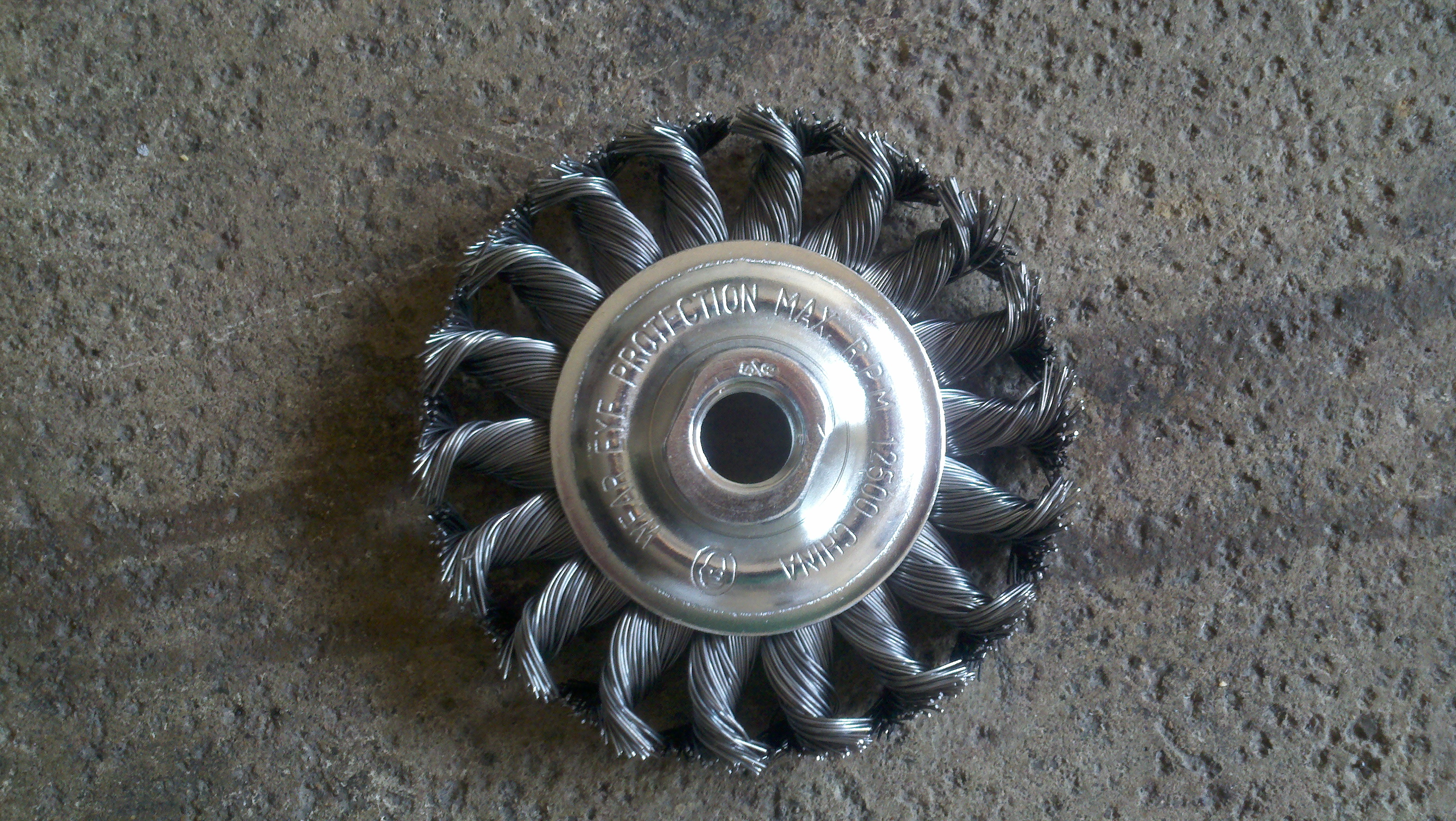
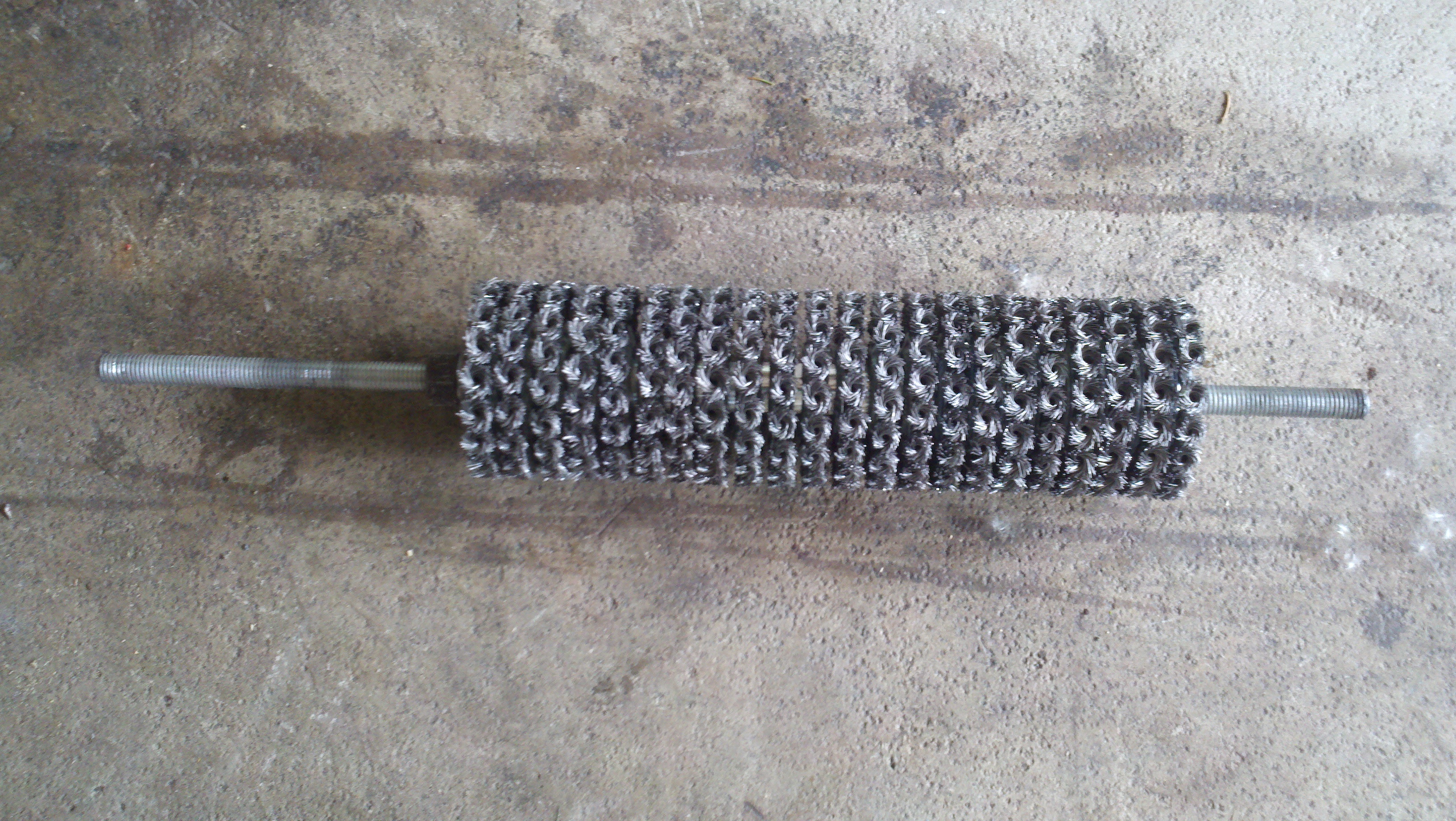
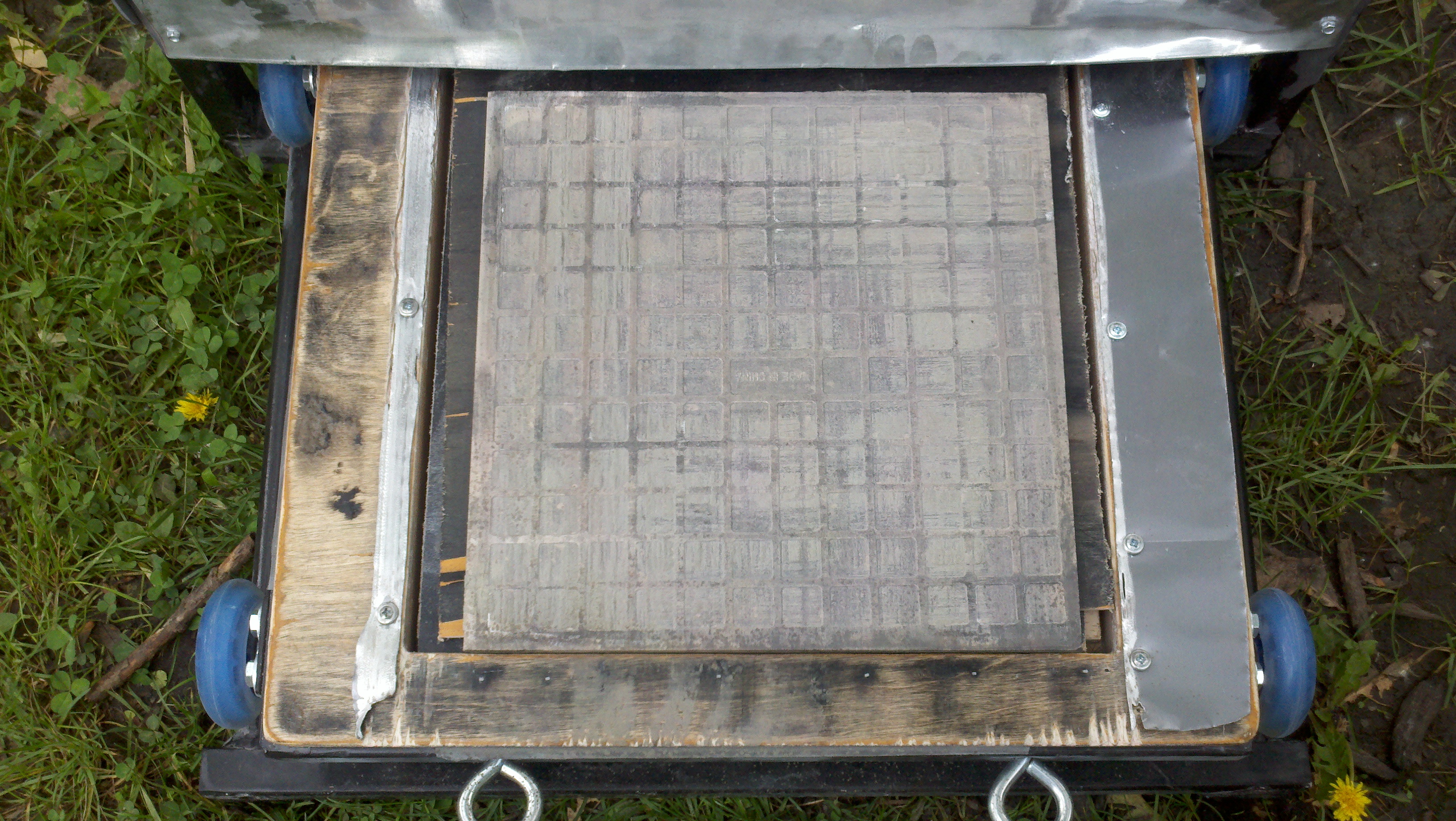
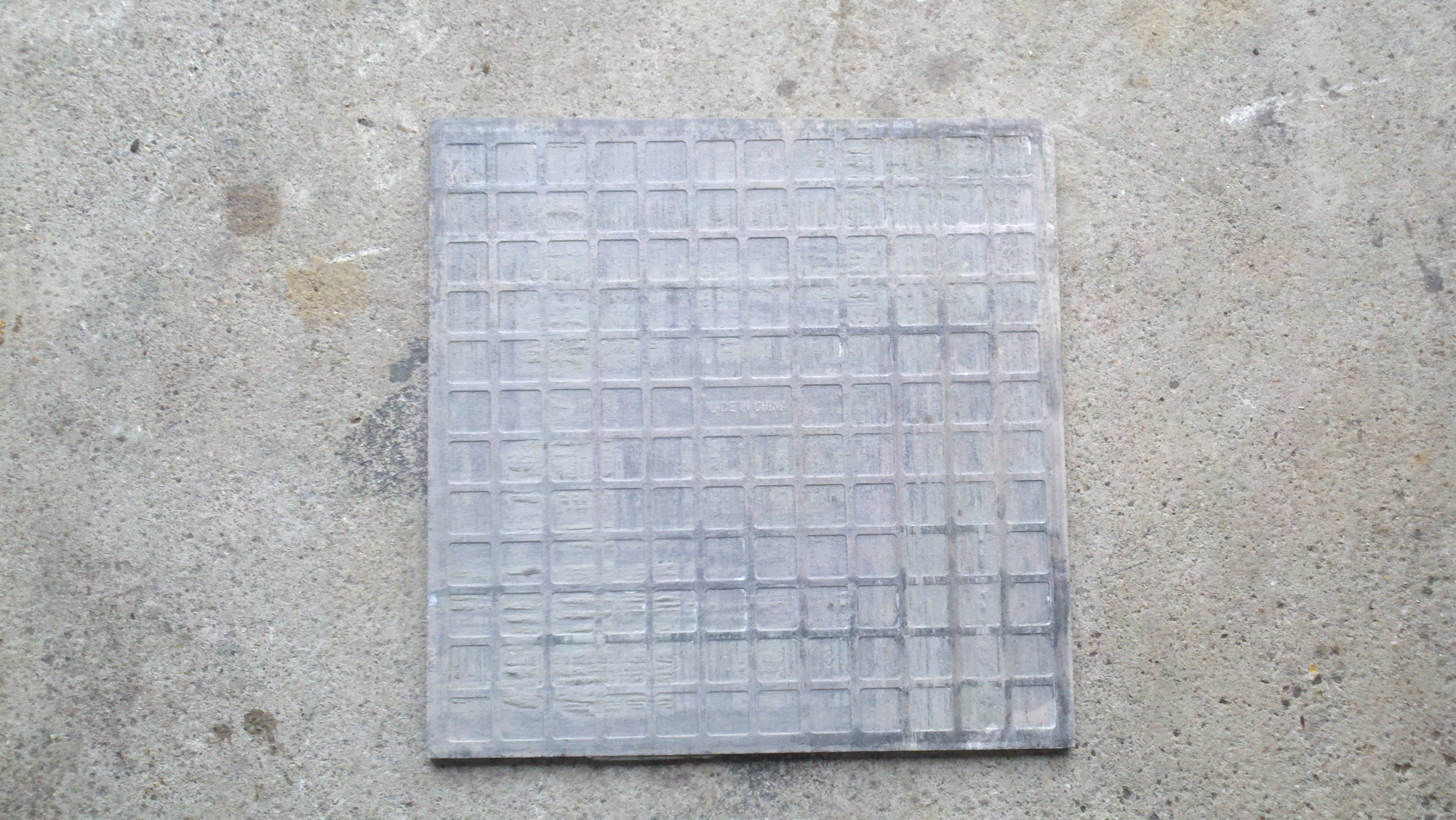
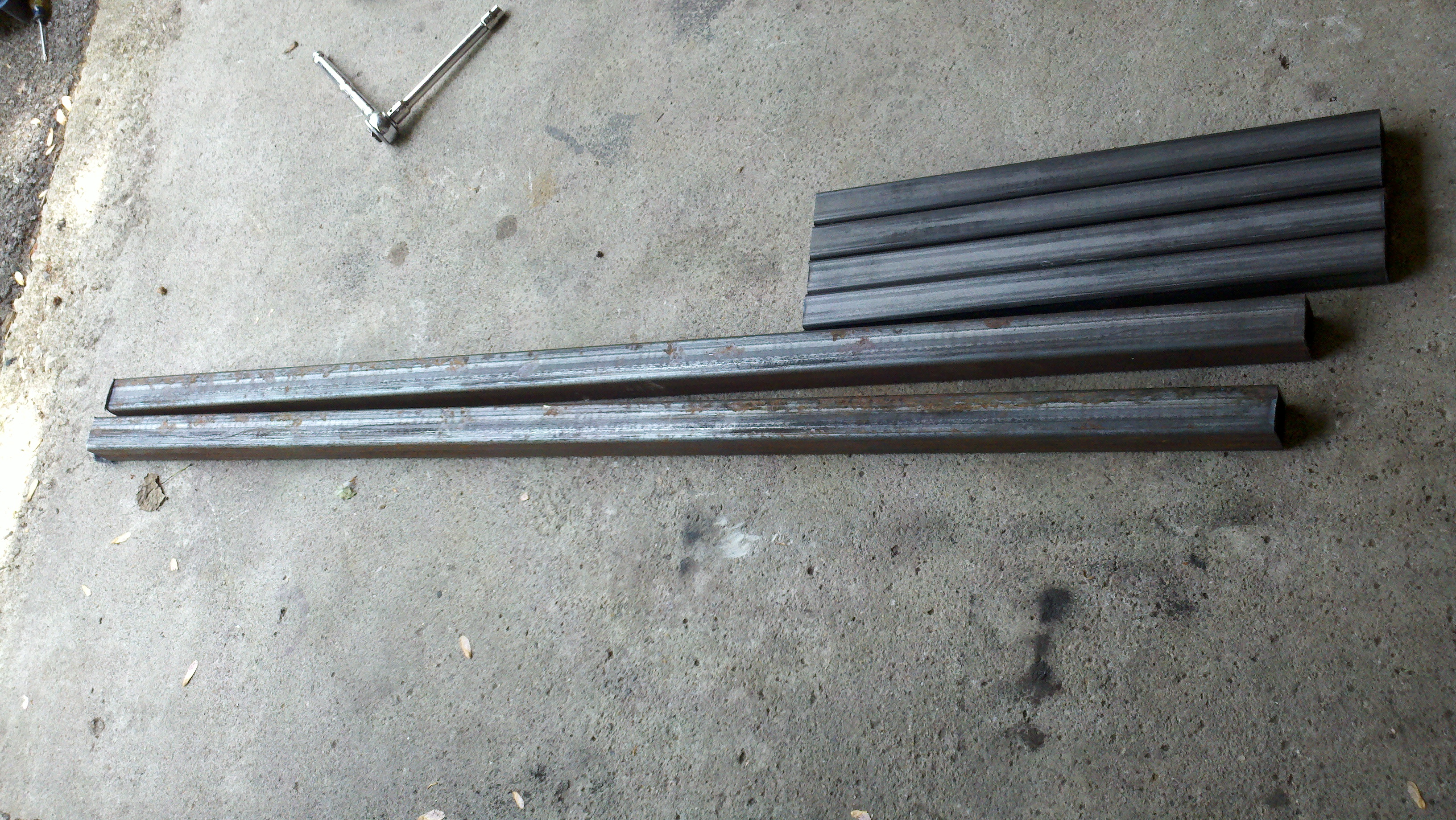
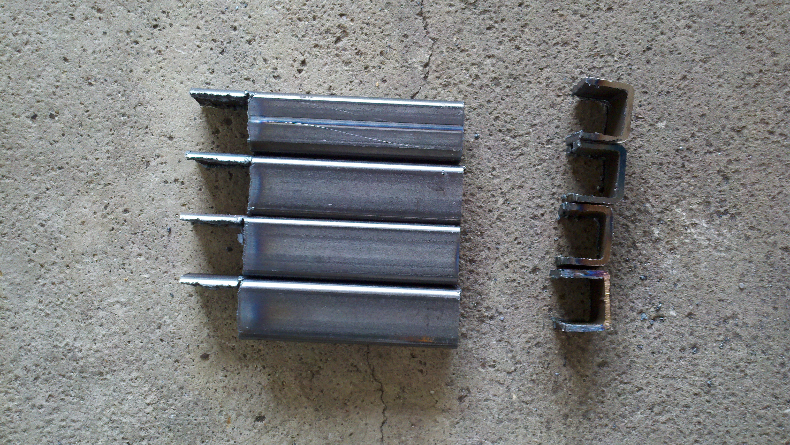
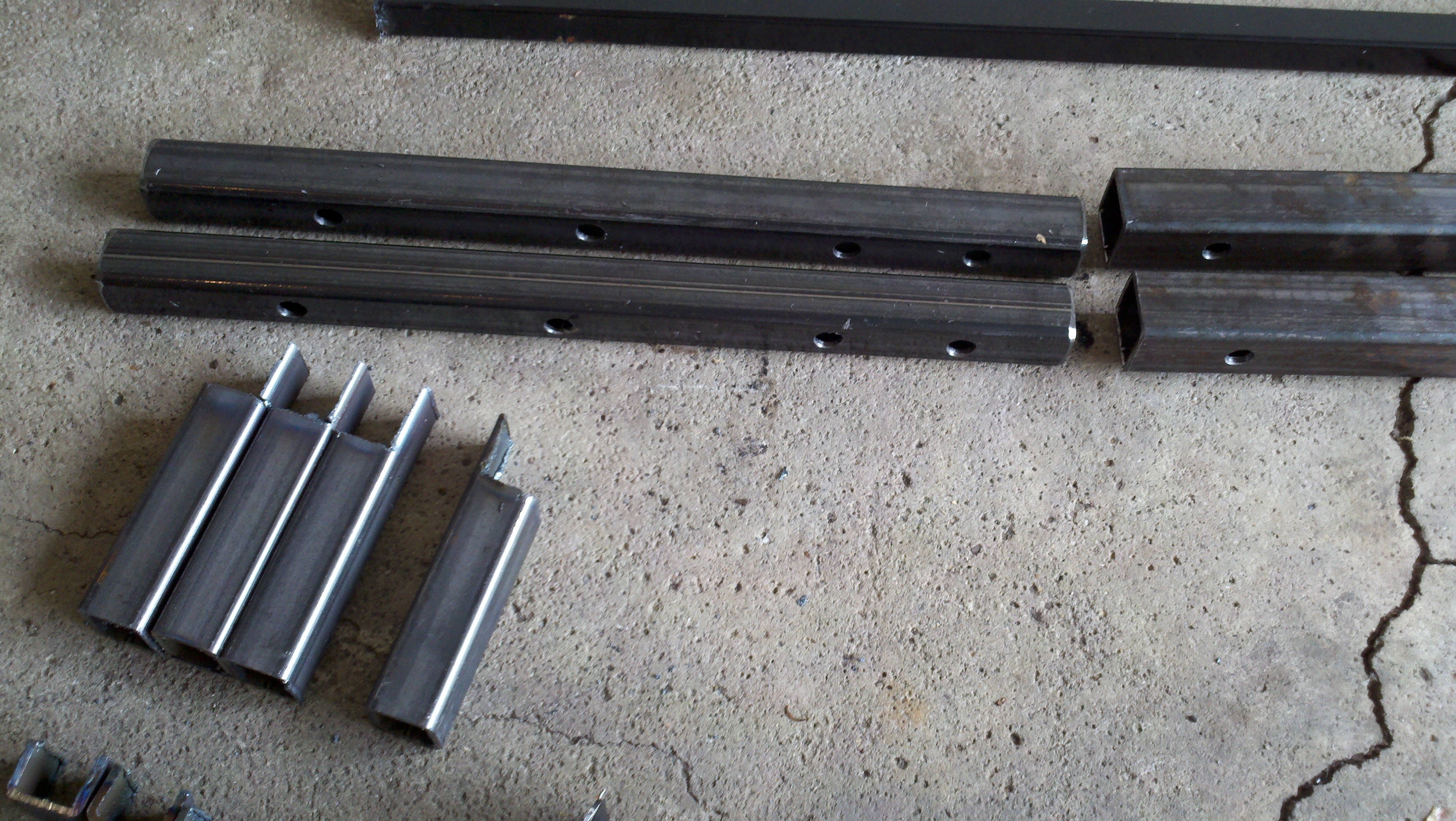
Thin-Set Mortar Planer
...IN PROGRESS... |
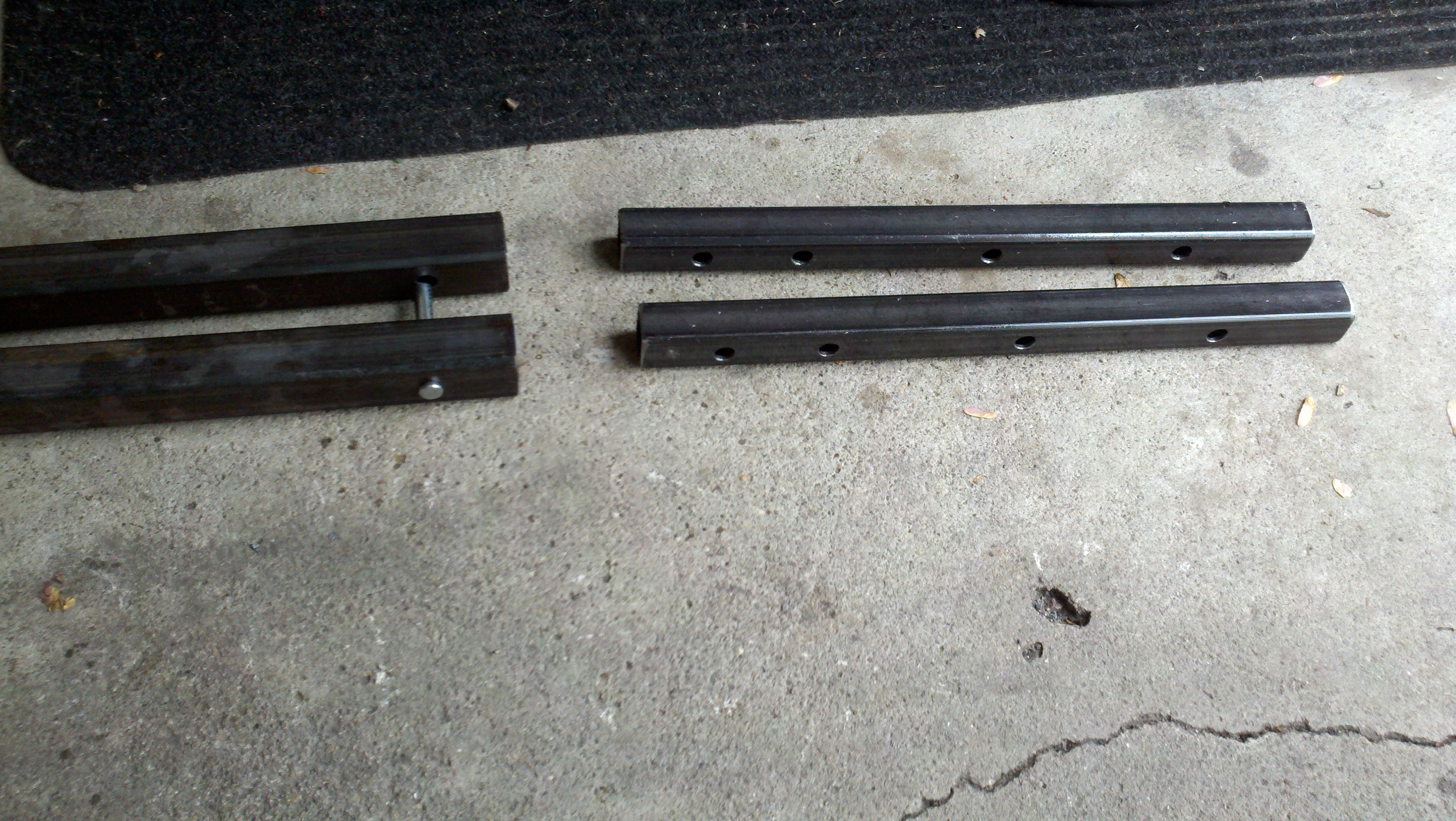
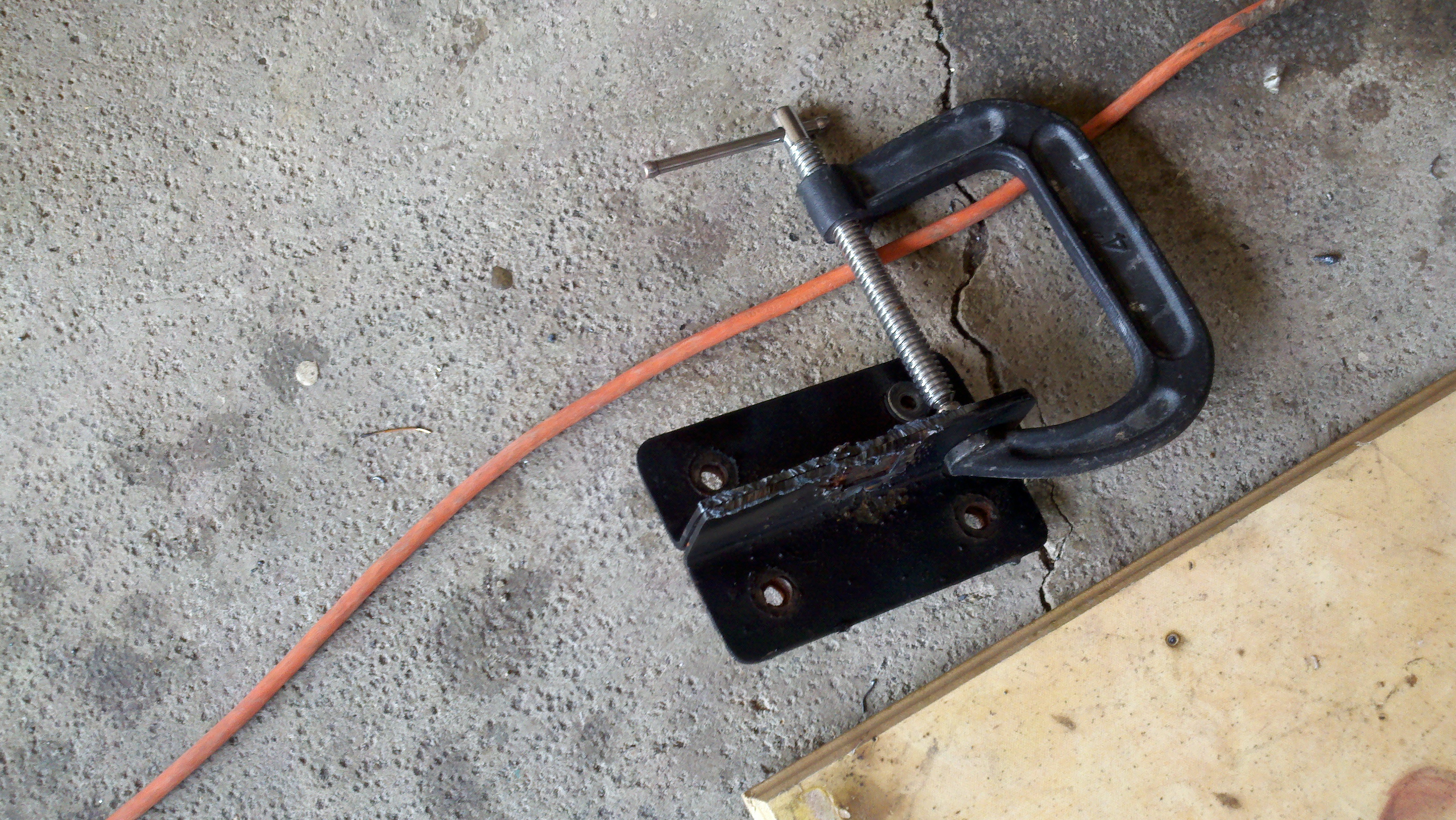
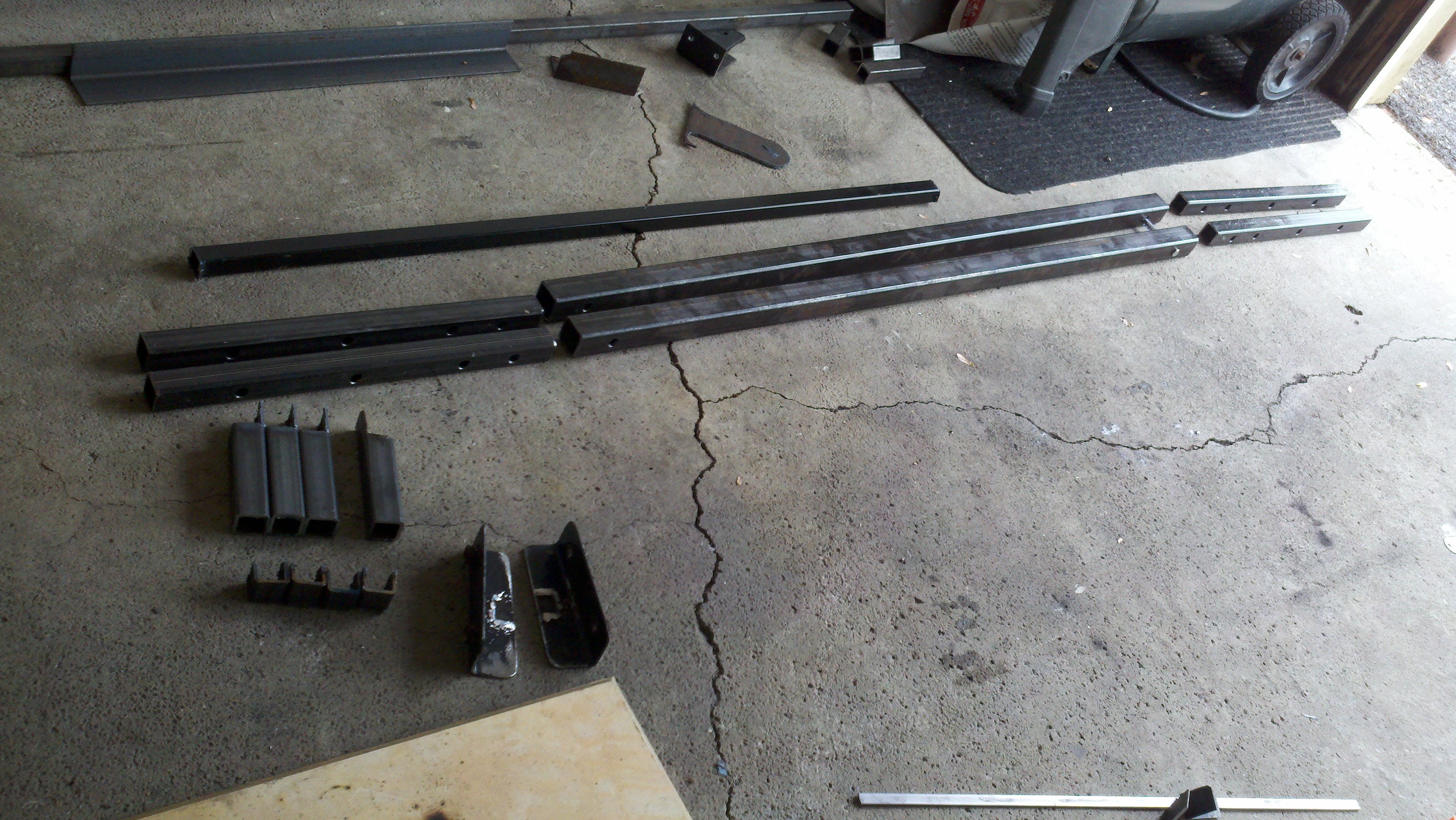
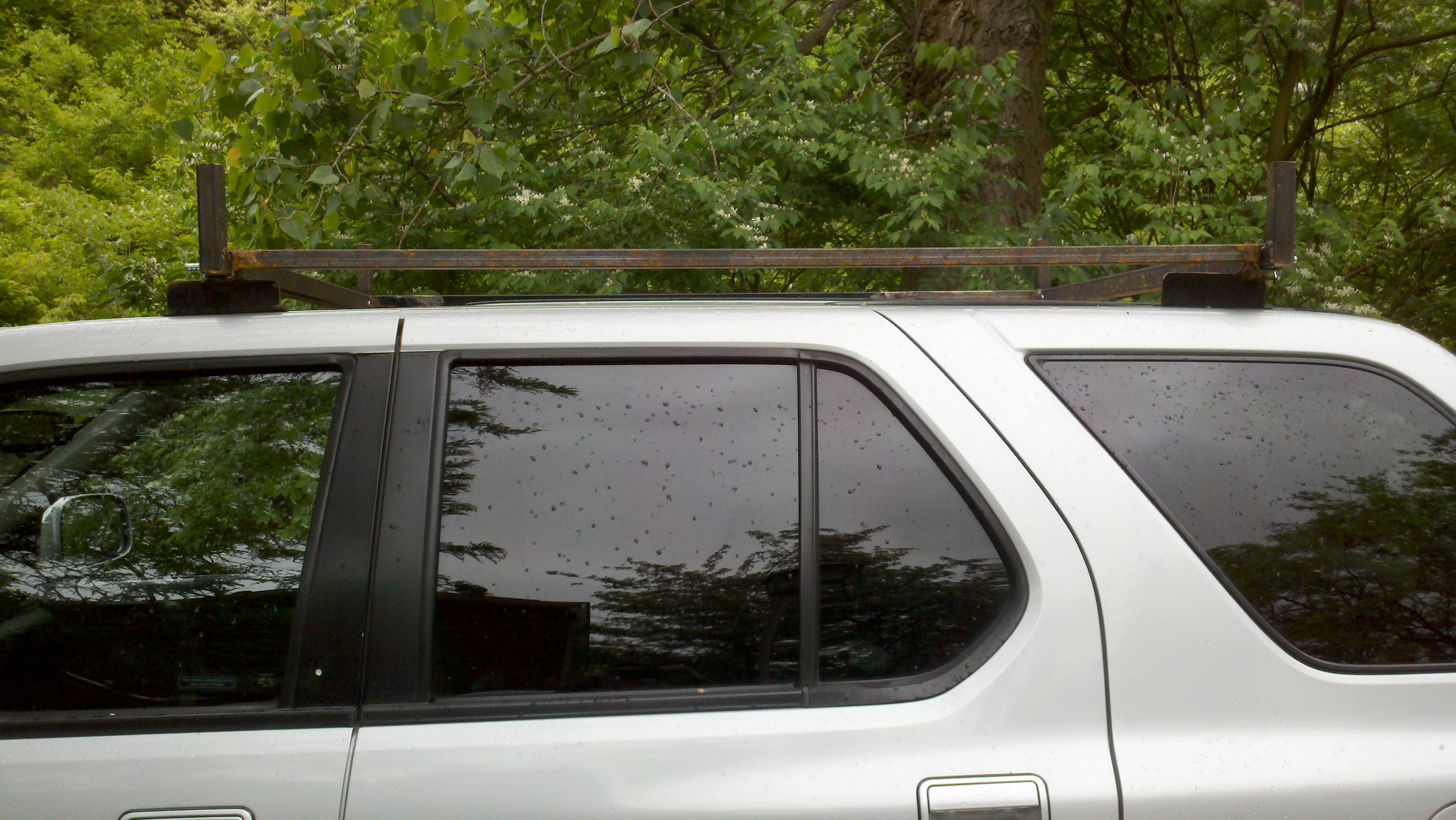
| 1999 Honda Passport Roof Rack
...IN PROGRESS |

![]()